73 KiB
1 AitalMAC UI
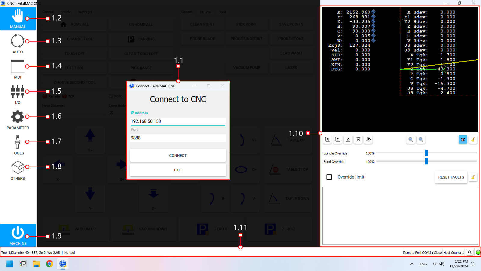 Figure 1: The AitalMAC application User Interface as it's displayed before connecting
The software interface is divided into distinct sections, each serving a specific purpose. Below is a breakdown of the main components:
-
- Connection Status: Enables users to connect to the CNC controller.
- Behavior: When the software connects to the CNC controller automatically at startup, this page is skipped, and users are taken directly to the manual interface.
-
Activity Bar (Left Side)
A vertical panel located on the left side of the interface. It is used to switch between different pages or activities within the software, each corresponding to a specific function or operation of the CNC machine.
- Manual: Access the manual control page for direct machine manipulation and jogging.
- Auto: Switch to automatic operation, where preprogrammed toolpaths are executed.
- MDI (Manual Data Input): Input and execute G-code commands manually.
- I/O: Monitor digital Input/Output signals of the machine and view machine working hours.
- Parameters: Navigate to the parameters page for configuring machine settings and system variables.
- Tools: Access Tool Manager, where you can create tools, set feeds and speeds for manual operations, and configure tool offsets.
- Others: Various additional tools are available, most notably the Remote Control settings.
- Machine: This button enables/disables machine operations. Colors indicate enabled state. Machine faults prevent activation and display errors.
-
- 3D Preview: Displays a visual representation of the machine or toolpath, aiding in real-time monitoring.
- Machine Position and Torque Information: Numerical or graphical data about the machine's current position and applied torque.
- Message log area: Displays system messages, errors, and warnings for easy troubleshooting and status updates.
-
A toolbar on the bottom section of the interface displaying key information about the current machine:
- Loaded Tool: Indicates the currently loaded tool in the CNC machine.
- Other Info: Including machine status, active program, and system warnings.
1.1 Connect window
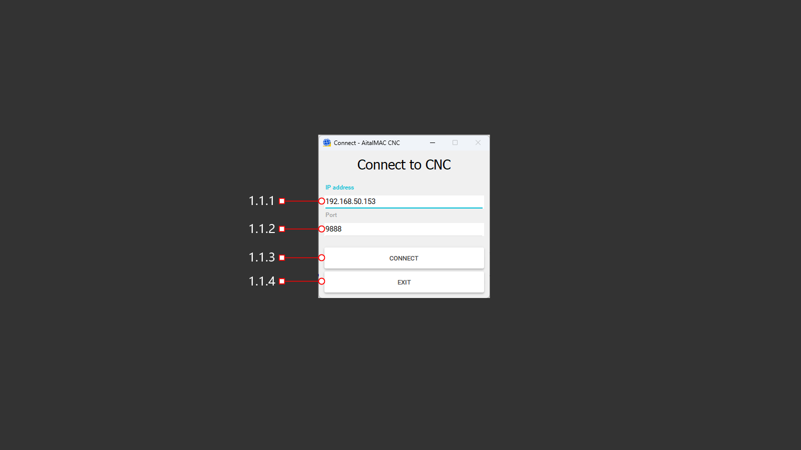 Figure 1.1: The Connect window which only appears when automatic connection fails
The Connection Window appears when the software starts up and cannot automatically connect to the CNC controller. It allows users to establish communication between the software and the CNC controller.
- Purpose: Ensures that the software can connect to the CNC controller hardware before proceeding to other activities.
- Behavior:
- If a connection is successfully established at startup, this page is bypassed, and the user is taken directly to the manual interface.
- If the connection fails, this page remains active, providing the user with options to retry the connection or exit the program.
1.1.1 IP Address
The text input field to enter the network IP address of the CNC machine for establishing a connection.
- Default Value: The default IP address for a single AitalMAC machine is 192.168.50.152 (for machines within a line, this increments for each machine—153, 154, and so on)
1.1.2 Port
The numerical input field to specify the port number required for the connection.
- Default Value: The default port for AitalMAC machines is 9888.
1.1.3 Connect
The button to initiate the connection process using the details entered in the IP Address and Port fields.
1.1.4 Exit
The button to close the program.
1.2 Manual
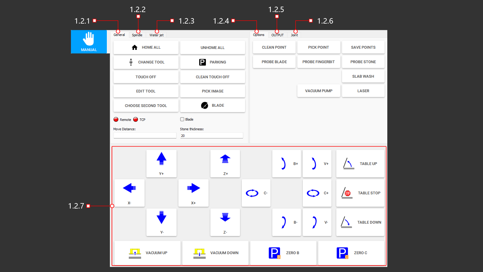 Figure 1.2: Manual page of the AitalMAC Application
The Manual Page provides direct access to machine operations and motion control. This interface enables operators to manually control various basic machine functions.
-
- Provides buttons for executing common machine functions.
-
- Activates spindle rotation according to the settings specified in the tool's database.
- Includes a button to change the spindle rotation direction (clockwise or counterclockwise), essential for tools requiring specific rotational directions.
-
- Controls for raising and lowering the water jet nozzle.
- Start and stop the high-pressure pump.
-
- Includes buttons for additional machine functions.
-
- Operates the main water supply valve.
- Activates auxiliary water systems.
- Controls cooling system water flow.
-
- Allows bypassing of axis limit sensors to move beyond axis limits.
- Note: This function should only be used with caution by authorized personnel.
-
- Enables movement along all axes.
- Operates table controls, such as lifting and lowering.
- Controls the vacuum lifter for slabs.
- Parks the machine along the B and C axes.
1.2.1 General
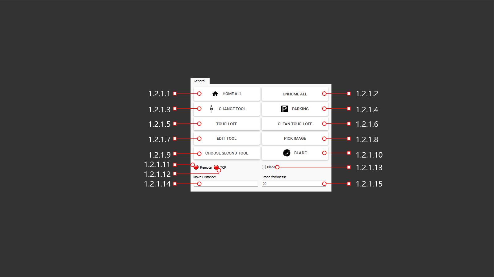 Figure 1.2.1: General tab within the manual page
The General control tab provides buttons for executing common machine functions, which will be described in detail in the following chapters.
1.2.1.1 Home All
The HOME ALL function moves all machine axes to their reference (home) positions.
- For machines equipped with motors featuring absolute encoders (which is the case for most AitalMAC machines), the home position is provisional.
- The provisional home position will be overwritten by the absolute encoder position when the Machine On button is pressed.
1.2.1.2 Unhome All
Clears the homed status of all machine axes.
1.2.1.3 Change Tool
Opens the tool list window, allowing the user to select and switch the active tool. This window can be used to set either the main or secondary tool, depending on the button used to access it. When accessed through "Change Tool," the selected tool is set as the main active tool. Note that the secondary tool option is only available on 5-axis saws.
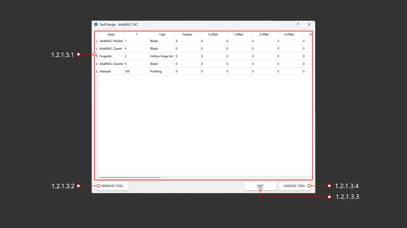 Figure 1.2.1.3: Tool change window
1.2.1.3.1 Tool List
A panel of tools stored in memory that the machine uses to operate.
1.2.1.3.2 Remove Tool
This button initiates a tool change operation to unload the currently used tool. On AitalMAC base model saws without automatic or manual tool change stations, the tool will simply be removed from memory. For machines with tool stations or positions, the automatic tool change routine will unload the current tool.
1.2.1.3.3 Exit
Closes the tool selection panel.
1.2.1.3.4 Choose Tool
This button activates the selected tool from the tool list for use on the machine. The tool list window can be accessed in two ways:
-
Selecting the main tool: Use Change Tool to open the tool list window and select the main active tool. On AitalMAC base model saws, the tool is loaded into memory. On machines with tool stations, the selected tool is automatically loaded or exchanged.
-
Selecting the secondary tool: Use Choose Second Tool (specific to 5-axis saws) to open the tool list window. The selected tool is set as the secondary tool, stored in memory, and displayed at the bottom of the application, separated from the main tool by a pipe symbol (|).
The designation of a tool as main or secondary depends entirely on how the tool list window is accessed.
1.2.1.4 Parking
This button moves the machine to a designated parking position as defined in the parameters. Parking is not always safe, particularly when the machine is engaged with the material, such as during a 45-degree miter cut. Always ensure the machine is in a safe state before initiating the parking operation.
1.2.1.5 Touch-Off
Moves the machine origin reference point to the current tool position, effectively redefining the machine’s working coordinates.
If this action is performed by mistake and then confirmed, a blue line will appear in the 3D area to indicate the offset. It is advised to clear any accidentally applied touch-offs to prevent potential errors or unexpected behaviors.
1.2.1.6 Clean Touch Off
Clears and resets the current touch-off reference point.
1.2.1.7 Edit Tool
Opens a dialog to modify currently loaded main tool parameters.
 Figure 1.2.1.7: Edit tool window
Introduction to Tool Management
The tool management system in the AitalMAC application is inherited from AitekCAM, a CNC Stone Machining Center application initially developed for routing operations and later extended to include blade functionality. To maintain compatibility, AitalMAC still allows tools to be synced with AitekCAM. However, the way tool parameters are used differs significantly between the two systems. Additionally, programs post-processed by Pegasus CAD/CAM do not utilize the tool parameters defined within the AitalMAC application, as Pegasus relies on its own set of parameters for program execution.
In AitekCAM, parameters like tool types play a central role in defining the behavior of programs created within the CAM environment. These parameters influence the operation paths, machining logic, and other critical aspects of toolpath generation. In contrast, AitalMAC uses tool types primarily to manage conflicts between tools and operations. For example, in AitalMAC, users can only access the X-Y Cut page—designed specifically for blade tools—if the main loaded tool is of the blade type. In this context, tool types help ensure logical compatibility between operations and tool assignments rather than defining program behavior.
It is important to recognize that many of these parameters are influenced by the history of development. As a result, some parameters may appear unnecessary or out of place unless this historical context is considered. For instance, parameters like speeds and feeds are heavily utilized in AitalMAC, while others, such as safe position, are included solely for compatibility with AitekCAM, where they are still actively used. Understanding this distinction can help users better navigate and make sense of the tool management system in AitalMAC.
1.2.1.7.1 Basic
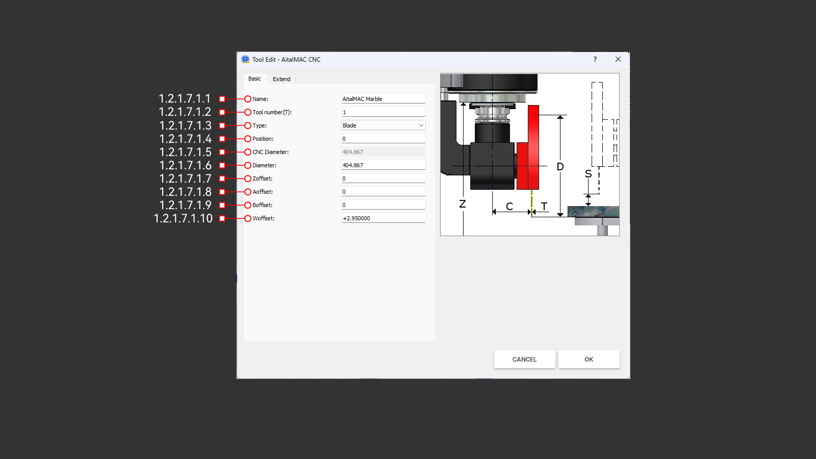 Figure 1.2.1.7.1: Basic parameters tab of the edit tool window
The Basic tab contains the essential parameters required to define a valid tool. These include the tool's name, type, number, position in the tool change sequence, diameter, and axis offsets.
1.2.1.7.1.1 Name
The Name field specifies the unique identifier for the tool. It serves as a label to easily recognize and distinguish the tool. The name should be descriptive enough to provide clarity about the tool's purpose or type (e.g., "Finber Bit 20mm" or "Saw Blade Marble 450mm"). Proper naming conventions ensure smooth operation, especially when managing multiple tools.
1.2.1.7.1.2 Tool Number (T)
The Tool Number (T) is a unique identifier used by the machine's logic to manage and reference tools during operations. The program ensures this number is unique. If a duplicate tool number is entered, an error will occur, and the program will automatically compile and assign the next viable unique number before saving the tool. This prevents conflicts and ensures accurate tool handling in the machining process.
1.2.1.7.1.3 Type
This field allows you to select the type of tool being used in the operation from a dropdown list. Available options include tools such as a drill, blade, finger bit, and others. The selected tool type is validated to ensure compatibility with the operation being performed. For instance, a probing operation requiring a finger bit will check that the second loaded tool is not a blade, as using an incorrect tool could lead to unexpected behaviors or errors.
If the wrong tool type is detected, the machine will stop and display an error message. This system safeguards against potential issues, maintaining safety and operational precision. Maintaining consistency between AitalMAC and Pegasus applications by matching tool types is strongly recommended, as future updates to AitalMAC may introduce similar restrictions, such as specific tool requirements for functions like drilling holes.
Tool Types in the Dropdown List:
- Profiling: Tools used by CNC Machining Centers to shape the edges of the stone. This type is included for AitekCAM compatibility purposes.
- Drill: Commonly used for creating cylindrical holes in materials. Drills are allowed as secondary tools in the AitalMAC application and can also be used in Pegasus to program drilling hole strategies, particularly for finishing concave corners that cannot be reached by a blade. It is recommended to maintain consistency by explicitly setting drills as such in both AitalMAC and Pegasus applications.
- Water Slot: Also known as calibration wheels, these tools are included for AitekCAM compatibility purposes. Operators will often set tools of this type due to their distinct appearance compared to a finger bit. While there are no strict limitations within the AitalMAC application, consistency with AitekCAM ensures smooth operation.
- Tap: Deprecated and maintained for legacy machines only, slated to be removed.
- Blade: Ensures compatibility for cutting tasks that require tools classified as "blade" type. The AitalMAC application enforces strict limitations, allowing only tools of this type to perform certain operations to ensure precision and safety. Properly selecting the tool type aligns the application’s operations with the intended tool usage, minimizing risks and maximizing efficiency. Although Pegasus and AitalMAC applications operate independently without strict integration, maintaining consistency in tool type settings across both systems is highly recommended. This practice simplifies workflows and ensures readiness for future updates and improvements to both applications.
- Finger Bit: Commonly used for CNC Machining Centers to cut sinks out, this tool type is also included for compatibility with AitekCAM rather than serving any specific function within the AitalMAC application. It is not recommended as the secondary tool for bridge saws, as the hollow finger bit tool type is better suited for such tasks, ensuring optimal compatibility and performance.
- Groove Bit: Maintained solely for compatibility with AitekCAM, as even the slope program within AitalMAC does not require this type of tool.
- Hollow Finger Bit: This is the correct type for the secondary tool for AitalMAC saw machines. Choose this type rather than the Finger Bit, as it is better suited for the type of processing performed by Pegasus, which runs steps in a spiral fashion.
1.2.1.7.1.4 Position
This setting specifies the position of the tool within the machine's magazine. On machines equipped with an automatic tool change function, the available positions are typically numbered, such as 1 to 27. These numbered positions correspond to the pockets in the magazine.
- Position 0: Reserved for manual tool changes. When a tool is assigned to Position 0, the machine will move to the manual tool change position and await user confirmation after the tool change is completed. This behavior is consistent regardless of whether the current and requested tool are both assigned to Position 0.
- Positions 1 to 27: These positions are used for automatic tool changes. If two tools are assigned to the same position, the tool change sequence is skipped because it is interpreted as stacked tools. This allows seamless transitions without requiring additional tool change operations.
- Positions 28 and Higher: These positions are also reserved for manual tool changes. However, unlike Position 0, if two tools share the same position number, the tool change sequence is skipped as it is interpreted as stacked tools.
It is important to note that Position 0 has unique behavior: the machine always moves to the manual tool change position and waits for user confirmation, even if the current and requested tool are both in Position 0. For positions beyond the magazine's automatic range (e.g., 28 and higher), the tool change sequence behaves similarly to stacked tools, skipping the sequence when tools share the same position number.
1.2.1.7.1.5 CNC Diameter
The CNC diameter is a view-only field showing the calculated diameter used for tool radius compensation (e.g., G41-G42), commonly applied when running tools along the edge of the material on CNC machining centers. It is derived as:
CNC Diameter = Diameter + (Removal × 2)
The Removal value, specified in the Extend tab, adds an offset to the tool radius to leave surplus material for subsequent tools in a multi-step grinding process. Each tool in the sequence progressively removes material, refining the surface left by the previous tool. Only the final tool, with no "Removal" offset, grinds the material to the programmed finished size using its actual measured diameter.
When probing the tool diameter on CNC machining centers, the machine will adjust both CNC and base diameters while keeping the Removal constant.
It is important to note that on 5-axis bridge saw machines, which predominantly use blade saw tools operating vertically and approaching the material from the top, removal offsets are not applied to depth. Removal compensation (via G41-G42) works exclusively on the XY plane, where the spindle approaches horizontally, as is typical for CNC machining centers. For 5-axis bridge saws, removal compensation is not applicable to either edge or depth, as the nature of the cutting process differs significantly from CNC machining centers.
1.2.1.7.1.6 Diameter
This is the actual, physical diameter of the tool as measured and entered by the operator when installing a new tool. The base diameter serves as the foundation for calculating the CNC diameter and represents the real dimensions of the tool itself. It ensures accurate toolpath calculations and material removal during machining processes.
For blade-type tools, the diameter can be probed by the machine. After a successful probing sequence, the measured diameter is automatically updated in the system, ensuring precise cutting operations and alignment.
1.2.1.7.1.7 Zoffset
This offset is applied along the Z axis using G43 and removed with G49, subtracting the tool’s offset from the current axis position. In most CNC machining centers with vertical spindles, tool length compensation occurs on the Z axis. However, on AitalMAC 5-axis bridge saws (and similar 5-axis machines), the tool length is compensated on the W axis, which runs parallel to the spindle’s axis.
1.2.1.7.1.8 Aoffset.
This offset applies to the A axis, which is typically not used on most AitalMAC machines. Keep it set to 0.
1.2.1.7.1.9 Boffset
This offset is associated with the B axis. On 5-axis bridge saws, where the B axis exists physically, Boffset is typically left at 0. However, on AitalMAC's CNC machining centers—which do not actually have a B axis—Boffset is repurposed for tool diameter probing.
During diameter probing, the offset designated as Boffset is temporarily applied on the Z axis to position the tool at the correct “probing height.” This probing height differs from the normal “working height,” which is managed by Zoffset. Therefore, Boffset does not serve as a tool-length offset during regular cutting operations; it is used solely to set the correct probing position for diameter measurement on machines without a physical B axis.
1.2.1.7.1.10 Woffset
Woffset is an offset applied along the W axis, which aligns with the main spindle axis where tools are mounted and acts as the tool length. This offset ensures accurate tool positioning on 5-axis machines by compensating for differences in tool geometry and mounting relative to the machine's pivot point.
For blade-type tools, the flange serves as the reference point for Woffset calculations. The flange provides a fixed and consistent mounting position, making it critical for precise alignment and operation.
Woffset is also applicable to all other tool types, including those not directly attached to the flange. In these cases, Woffset is calculated based on a theoretical flange position to maintain consistent functionality.
Pegasus software calculates Woffset for blade tools using the segment thickness and core thickness of the blade:
Woffset = (Segment Thickness - Core Thickness) / 2 + Core Thickness
This calculation assumes the blade is symmetrical. Operators must be aware that Pegasus sets Woffset automatically using this formula. For asymmetrical blades, operators must adjust parameters as though the blade were symmetrical to ensure proper machine operation.
Managing Woffset in Systems
- Without Tool Change Capability: On 5-axis machines without tool change support for CNC profiling tools, Pegasus software automatically manages Woffset, simplifying setup and ensuring precise cutting without manual intervention.
- With Tool Change Capability: On machines with tool change features, Woffset is managed within the AitalMAC application as the tool length offset. This applies to blades and other profiling tools, requiring operators to accurately set and maintain Woffset for reliable performance during tool changes.
Key Considerations
- Accurate Measurements: Measure segment and core thickness precisely.
- Symmetry Adjustment: Adjust parameters for asymmetrical blades, as Pegasus assumes symmetry.
- Software Integration: Identify whether Pegasus or AitalMAC handles Woffset in your workflow.
- Tool Consistency: Update Woffset settings for each tool type.
- Regular Calibration: Periodically verify Woffset settings to ensure accuracy.
Proper management of Woffset is essential for achieving high-quality and consistent cutting performance on 5-axis machines.
1.2.1.7.2 Extend
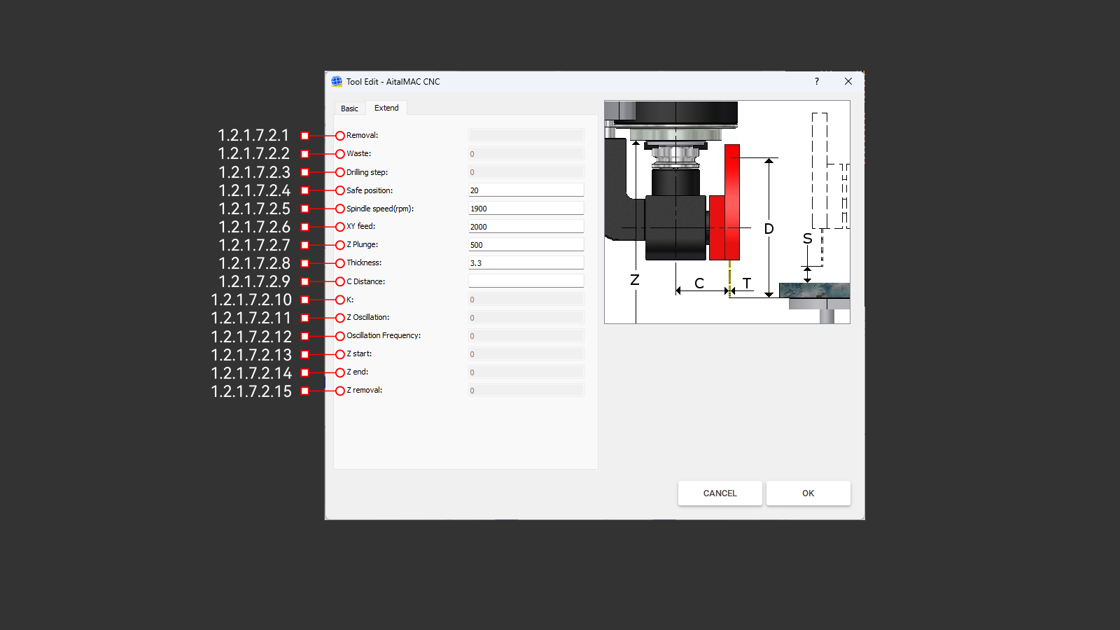 Figure 1.2.1.7.2: Extend parameters tab of the edit tool window
The Extend tab provides additional parameters for advanced tool setup and operation. While some of these parameters are optional, others—such as thickness, speed and feed settings—are essential for ensuring proper tool functionality.
1.2.1.7.2.1 Removal
The "Removal" is a crucial parameter that defines the additional offset added to the tool radius during CNC operations. This value is entered in the Extend tab and directly influences the calculation of the CNC diameter:
CNC Diameter = Diameter + (Removal × 2)
The primary purpose of the Removal is to leave surplus material for subsequent tools in a multi-step grinding process. Each tool in the sequence removes a layer of material, refining the surface left by the previous tool. This ensures that every tool can perform its task effectively, leading to a smooth and precise finish.
On CNC machining centers, removal is compensated by G41 and G42, which operate in the XY plane with the spindle vertical. This allows accurate edge compensation during machining. However, on 5-axis bridge saw machines, where blade tools approach the material from the top, removal does not influence depth adjustments.
Only the final tool in a grinding tool set operates without a Removal offset, using its exact diameter to achieve the programmed finished size. Proper configuration of the Removal parameter is essential for achieving precise machining results and maintaining consistent surface quality.
Availability: Removal is exclusively enabled for Profiling, Finger Bit, and Water Slot tool types. For all other tool types, this parameter remains inactive (greyed out).
1.2.1.7.2.2 Waste
This parameter is specific to tools used in CNC machining centers and exists solely for AitekCAM compatibility purposes. "Waste" is used by AitekCAM to generate programs that compensate for tool wear by adjusting the tool diameter between toolpath executions. This ensures that wear is accounted for before each new cycle.
In contrast, "Dynamic Wear" operates incrementally during the execution of a toolpath while the tool is in contact with the stone, allowing for more precise and adaptive compensation. While "Waste" is still present for legacy support, it has been largely replaced by "Dynamic Wear" in modern workflows.
Availability: Waste is exclusively enabled for Profiling, Finger Bit, and Water Slot tool types. For all other tool types, this parameter remains inactive (greyed out).
1.2.1.7.2.3 Drilling Step
This parameter is maintained for AitekCAM legacy compatibility and specifies the peck drilling depth used in generating peck drilling programs with drill tools.
Availability: Drilling Step is exclusively enabled for drill-type tools. For all other tool types, this parameter remains inactive (greyed out), as it is not applicable to them.
1.2.1.7.2.4 Safe Position
This parameter is included solely for compatibility with AitekCAM and does not directly operate within the AitalMAC application. It defines the distance of the tool above the material used during rapid movements within the generated program. Safe Position ensures that the tool clears the material safely when moving between machining operations, preventing collisions and optimizing workflow.
For AitalMAC Manual and Semi-Auto operations, the equivalent parameter is the Safety above the stone parameter, which is located in the Parameters page, not within the tool edit window where Safe Position is configured. This distinction ensures clarity in how these parameters are applied within their respective contexts.
1.2.1.7.2.5 Spindle Speed (RPM)
This parameter specifies the spindle revolutions per minute (RPM) and is valid in both AitalMAC and AitekCAM applications when using this tool. The spindle speed should be set considering the tool diameter, the material to be cut, and the recommendations provided by the tool manufacturer. Adhering to the recommended speed ensures optimal performance and prevents unnecessary wear or damage to the tool and material.
1.2.1.7.2.6 XY Feed
This parameter is valid in both AitalMAC and AitekCAM applications and specifies the feed rate in units per minute (units/min) that the tool will use while cutting the material in the X and Y directions. It is recommended to follow the feed rate suggested by the tool manufacturer, considering the material being processed. This parameter has no viability for drill tool type.
1.2.1.7.2.7 Z Plunge
Specifies the feed rate along the Z-axis during material entry. Set to 10%-15% of the XY Feed rate, with adjustments based on tool diameter, material properties, and manufacturer specifications. Ensures safe, effective plunging. Applicable in both AitalMAC and AitekCAM applications.
1.2.1.7.2.8 Thickness
Exclusive to blade-type tools, this parameter is valid in both AitekCAM and AitalMAC applications. It is used in semi-automatic processing to precisely adjust machine movements between cuts, compensating for blade thickness. Only enabbled for tools of Blade-tool type.
1.2.1.7.2.9 C Distance
The C Distance parameter does not function within the AitalMAC application. It was originally exclusive to AitekCAM for blade tools, where it served as a basic kinematics pivot offset for 4-axis machines. This parameter is now deprecated in AitekCAM and slated for removal from AitalMAC in future versions. Users of AitalMAC versions newer than this documentation may no longer see this parameter.
1.2.1.7.2.10 K
The K parameter is exclusive to Tap-tool type, which are slated for removal. This parameter may no longer be present in AitalMAC application versions released after the date of this documentation.
1.2.1.7.2.11 Z Oscillation
The Z Oscillation parameter is not used in the AitalMAC application and is exclusive to AitekCAM. It is valid only for Profiling and Finger Bit tools and specifies the wave height for oscillating toolpaths. When set to a non-zero value, it creates a wave-like motion along the Z-axis. The parameter can also take negative values, causing the entire wave to remain below the default working height.
This feature is used to ensure consistent tool wear along the entire length or to minimize visible lines in the material after processing.
1.2.1.7.2.12 Oscillation Frequency
Oscillation Frequency is closely related to the Z Oscillation parameter and determines the frequency of the wave generated when Z Oscillation is non-zero. The frequency is defined as half the wavelength of the wave. This parameter just like "Z Oscillation" is not used in the AitalMAC application and is exclusive to AitekCAM, applicable only to Profiling and Finger Bit tools.
1.2.1.7.2.13 Z Start
Exclusive to AitekCAM and only applicable to Groove Bit tool type, this parameter defines the starting height offset added to the tool's default working height. A negative value causes the tool to plunge deeper into the material. Groove Bits are designed for single-line segment paths in AitekCAM, enabling sloping linear paths when used in conjunction with Z End.
1.2.1.7.2.14 Z End
Exclusive to AitekCAM and only applicable to Groove Bit tool type, this parameter defines the ending height offset added to the tool's default working height. Like Z Start, a negative value causes a deeper plunge into the material. Together with Z Start, it facilitates the creation of sloping linear paths for single-line segment operations.
1.2.1.7.2.15 Z Removal
Exclusive to AitekCAM and only applicable to Groove Bit tool type, Z Removal is an additional offset applied to both Z Start and Z End. It simplifies creating a series of tools with incremental depths, where each subsequent Groove Bit plunges deeper. As Z Removal decreases, the tool plunges further into the material, allowing for precise control over depth. A Z Removal value of 0 aligns the start and end heights exactly with Z Start and Z End offsets.
1.2.1.7.3 Reference Image
This image provides a visual representation of key parameters in a standard format, helping users understand their purpose and functionality. Each tool type has its own dedicated image, serving as a guide for easier parameter interpretation.
1.2.1.7.4 Cancel
This button discards the last changes made to the tool settings and closes the tool edit window.
1.2.1.7.5 OK
This button saves the last changes made to the tool settings and closes the tool edit window.
1.2.1.8 Pick Image
Opens a window that uses the machine's camera to capture an image of the workbench and workpiece. It is recommended to park the machine before opening this window to ensure safe operation.
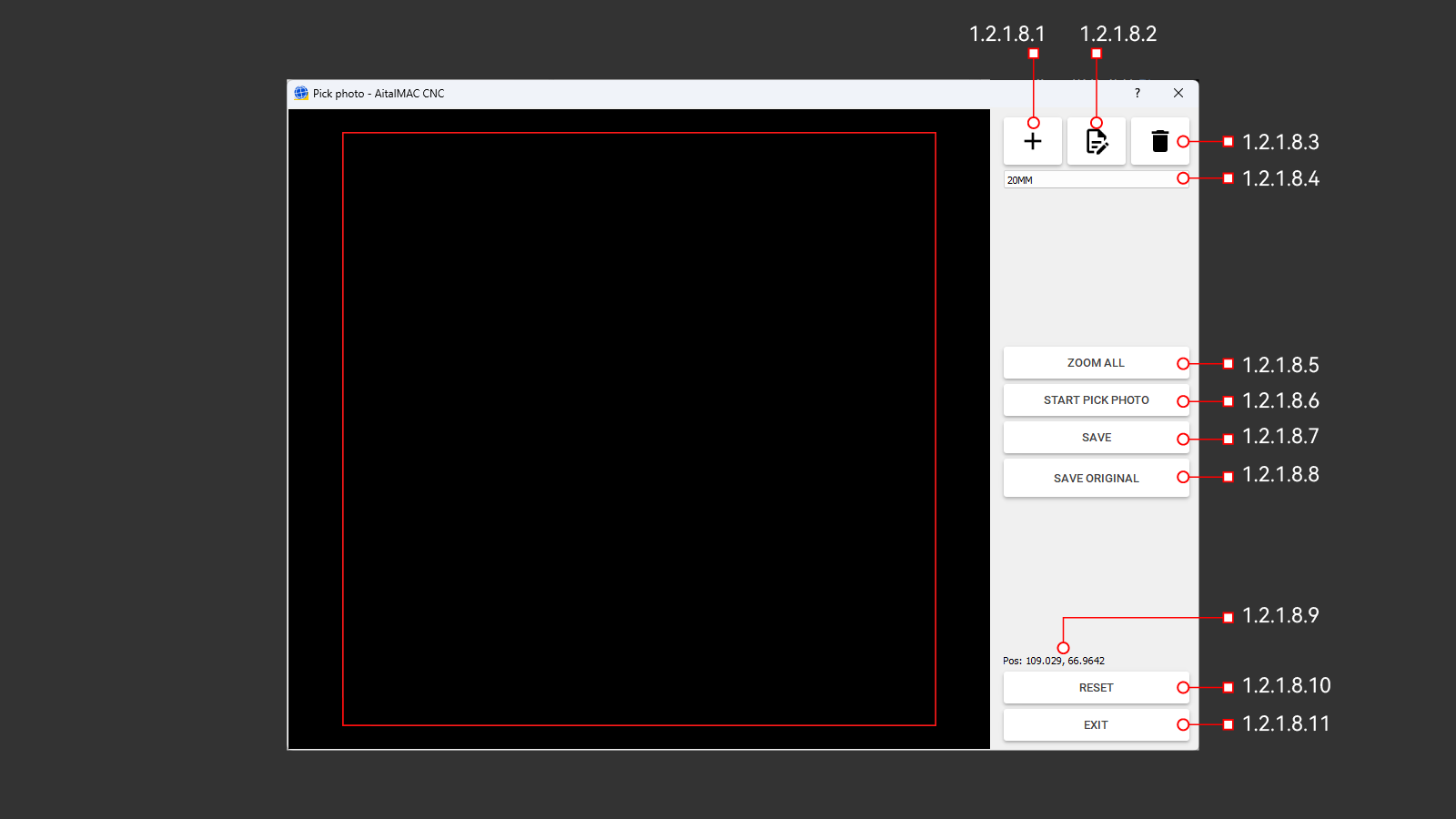 Figure 1.2.1.8: Pick Image window
1.2.1.8.1 Add
Opens a dialog to create a new camera configuration by entering a name. After confirmation, the configuration is saved as an empty, unparametrized setup and becomes the active configuration.
1.2.1.8.2 Edit
Opens a dialog to rename the active camera configuration. Changes can be confirmed or canceled to keep the original name.
1.2.1.8.3 Delete
Deletes the active camera configuration. Deletion is not allowed if it is the only configuration available.
1.2.1.8.4 Camera Configuration Selection
A dropdown list displaying all available camera configurations. AitalMAC supports managing multiple configurations, typically organized by material thickness. This can be avoided by using instead the camera configurations manager in Pegasus CAD/CAM, allowing the use of a single general configuration in the AitalMAC application while Pegasus handles specific adjustments for varying thicknesses. As of this document's writing, this setup is common on most AitalMAC brand machines.
1.2.1.8.5 Zoom All
Clicking this button adjusts the view to fit the entire photo within the view area.
1.2.1.8.6 Start Pick Photo
This button captures a photo of the material on the machine workbench. The machine must be powered on, and the camera must be properly connected and identified. After opening the Pick Image window, the user must wait for the countdown displayed on the button to ensure proper connection.
Clicking the button raises the Z-axis and moves the machine to the designated position to take the photo. Before using this function, ensure the machine is in a safe state, ideally parked, which can be done from the Manual page. This precaution prevents any unintended movements or collisions.
1.2.1.8.7 Save
Opens the Windows Save File dialog to save the image captured by the camera. The saved image is typically scaled to 1 pixel per mm based on the active camera configuration.
1.2.1.8.8 Save Original
Opens the Windows Save File dialog to save the raw image captured by the camera without applying any perspective or dimensional corrections. This option, available only for DSLR camera setups, allows users to save the original image for comparison with the corrected version to assess any potential deterioration in quality.
1.2.1.8.9 Pos
Displays the current machine X and Y positions. This feature is intended for debug purposes only.
1.2.1.8.10 Reset
This button reboots the camera system to reinitialize it when it becomes unresponsive. Pressing "Reset" closes the "Pick Image" window and initiates the reboot process. The AitalMAC application then enforces a 1-minute wait before allowing reentry to the "Pick Image" window.
Use this button if the camera displays a black picture or connection errors specific to the camera system occur. After the minute elapses, manually click the "Search" button 🔍, located in the bottom toolbar, to re-establish the connection and verify connectivity.
1.2.1.8.11 Exit
Closes the "Pick Image" window.
1.2.1.9 Choose Second Tool
This button opens the tool list window to select and switch the current secondary active tool. This functionality is specific to 5-axis saws.
The secondary tool complements the primary saw blade tool, typically mounted alongside it on the spindle. It can be a Hollow Finger Bit, a drill, or a waterslot/calibration tool type. Secondary tool selection is specific to the AitalMAC application, where certain operations validate the tool type. This selection has no impact on Pegasus CAD/CAM. For example, the Probe Fingerbit operation in AitalMAC will not function if a blade-type tool is set as the secondary tool. The secondary tool is displayed at the bottom of the application, alongside the primary tool, separated by a pipe symbol (|).
1.2.1.10 Blade
This button toggles the spindle on and off, starting at the main tool's speed(RPM) or, if the B axis is at position 0, the second tool's speed(RPM). The spindle speed can also be adjusted manually using the spindle override slider.
1.2.1.11 Remote Status Light
A status light on the monitor shows remote control status: red means inactive, green means active.
1.2.1.12 TCP Status Light
The TCP (Tool Center Point) status is exclusively relevant on the Manual Page of the AitalMAC application for 5-axis saw machines. The status light switches from red (inactive) to green (active) when the physical TCP switch on the machine panel is turned on.
With TCP inactive (red), axis movements and rotations are direct: linear axes move along their respective directions, and rotations affect only the machine parts directly connected to the motor for each axis.
When TCP is active (green), movements are tool (saw blade) related. Linear movements follow the blade's orientation, meaning if the tool is angled, the machine moves linearly along that angle. If the tool rotates 180 degrees, directional controls may feel reversed; for example, pressing the right button might move the machine left. While initially counterintuitive, this mode allows precise manual cutting at any angle. To simplify navigation, imagine the table moving under the stationary tool rather than the head moving.
Rotations with TCP active occur around the blade's tip, which serves as the center of rotation. This ensures that the cutting edge remains consistent in position during adjustments, preventing the tool from shifting to a different spot as it would with TCP off. Moving the B axis, which rotates the tool tip around the Y axis, can be counterintuitive. Rotating B so that the blade comes down will actually move the machine up. Most users lift Z to its maximum before attempting B rotation, which will not leave enough space and will trigger B limit warnings or errors. To avoid this, keep the Z axis lower during B movements or perform these movements with TCP off.
1.2.1.13 BLADE CHECK
Enables adding the blade thickness to move distance when moving orthogonally to the blade direction in TCP mode
1.2.1.14 MOVE DISTANCE
Sets the incremental distance for manual movements.
1.2.1.15 STONE THICKNESS
Indicates the thickness of the material (such as stone) that the machine must take into account. Indicated by hand or measured by machine.
1.2.2 SPINDLE
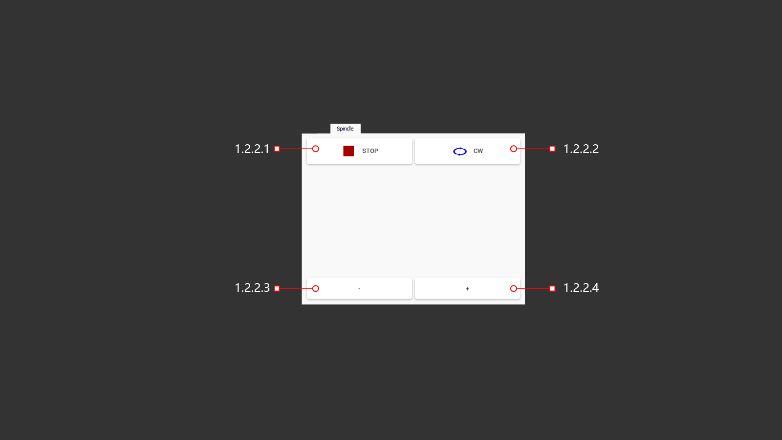
1.2.2.1 STOP
The spindle power button activates the rotation according to the settings specified in the tool's database, which is connected to the machine. This button is essential for the machine to function in manual mode, controlled by the operator.
1.2.2.2 CW
A button to change the direction of rotation of the spindle is provided. It can be set to rotate clockwise or counterclockwise, depending on the needs of the operator and the specific cutting tool being used. This feature is essential for proper operation of certain cutting tools, as it affects the direction of threaded fixation and the sharpening of cutting edges. The button is intended for manual use by the operator of the machine.
1.2.2.3 -
Reducing spindle speed rpm
1.2.2.4 +
Increasing spindle speed rpm
1.2.3 WATER JET
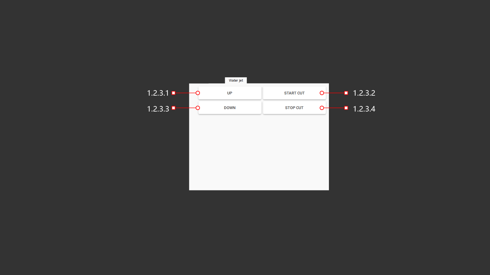
On this tab, you can find the main functions for configuring and checking the water jet. It can also be used for manual operation.
1.2.3.1 UP
A button for lifting the water jet module after completing the work. Once lifted, the previously used tool is automatically activated on the machine.
1.2.3.2 START CUT
Starting a water jet to begin cutting. After pressing the button, the pump begins to build up the necessary pressure and the valve opens to allow sand to flow into the cutting head. Once a set delay time has elapsed, as specified in the machine's settings, the water jet is ready to begin cutting.
1.2.3.3 DOWN
A button for lowering the water jet module. After lowering, the machine activates the water jet tool and the machine begins using the coordinate axis movement parameters according to the set tool parameters. The operator can then use the water jet in manual control mode.
1.2.3.4 STOP CUT
Stopping the water jet: After pressing the button, the sand supply valve is closed and the pump is then turned off to build up water pressure in the water jet system. This allows for the necessary time for cleaning the pipes from sand and for a smooth shut-off of the system.
1.2.4 Options
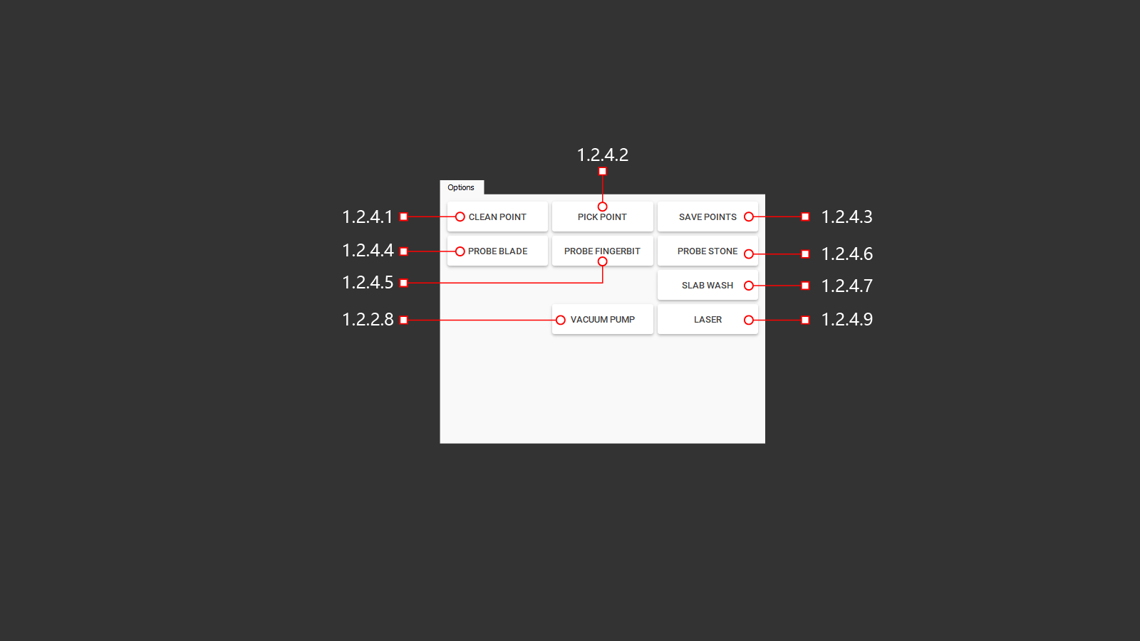
1.2.4.1 CLEAN POINT
Clear the internal memory where the previous coordinates of the points are stored to create a template. This is necessary to avoid overlapping new marked points with previously marked ones.
1.2.4.2 PICK POINT
Record points to create templates or necessary marks on the material. The operator receives them using a cross laser mounted on the machine, moving them along the axes to the desired location on the material. To record each point, you will need to click "Pick point".
1.2.4.3 SAVE POINTS
Saving all points created by the operator using a template or on the material for further work. The dot file is synchronized by the program to create a control program, where it is also possible to import a photo of the material from the desktop.
1.2.4.4 PROBE BLADE
The button for checking the diameter of the installed blade. After checking, the actual size of the blade will be recorded in the tool settings and the machine will execute commands with necessary corrections. This includes the depth of immersion into the worktable and the exit of the cut from the material, which helps to avoid collisions and incorrect cuts.
1.2.4.5 PROBE FINGERBIT
The button for checking the length of the installed milling cutter is located on the machine. After checking, the actual length of the cutter will be recorded in the tool parameters, and the machine will execute commands with the necessary adjustments. This ensures that the depth of immersion into the worktable and the beginning of milling are accurate, based on the thickness of the material being processed. This helps to avoid collisions and incorrect cuts, as well as any collisions with the material being machined.
1.2.4.6 PROBE STONE
Button for using a probe to study the thickness of the material to adjust the operation of the machine according to the program and in manual mode.
A button to check the thickness of the material used. Thickness adjustment is necessary for proper cutting with a blade and a water jet at an angle from 1° to 57° in order to maintain the overall dimensions of the part. For milling, this is the redefinition of the safety zone and the calculation of the material milling steps.
1.2.4.7 SLAB WASH
Turning on the watering can to clean the material from dirt
A button to turn on the water pressure cleaning system. This is necessary to use a vacuum lift for flat material weighing up to 500 kg. Before using the vacuum suction cups, the operator washes the contact points of the suction cups with the material.
1.2.4.8 VACUUM PUMP
A button to turn on the vacuum pump. When the pump is turned on, a suction force is created on the suction cups to lift and then move the material.
1.2.4.9 LASER
The laser line corresponds to the direction of the cutting blade and helps the operator to adjust the cutter to cut the material at the desired location.
1.2.5 OUTPUT
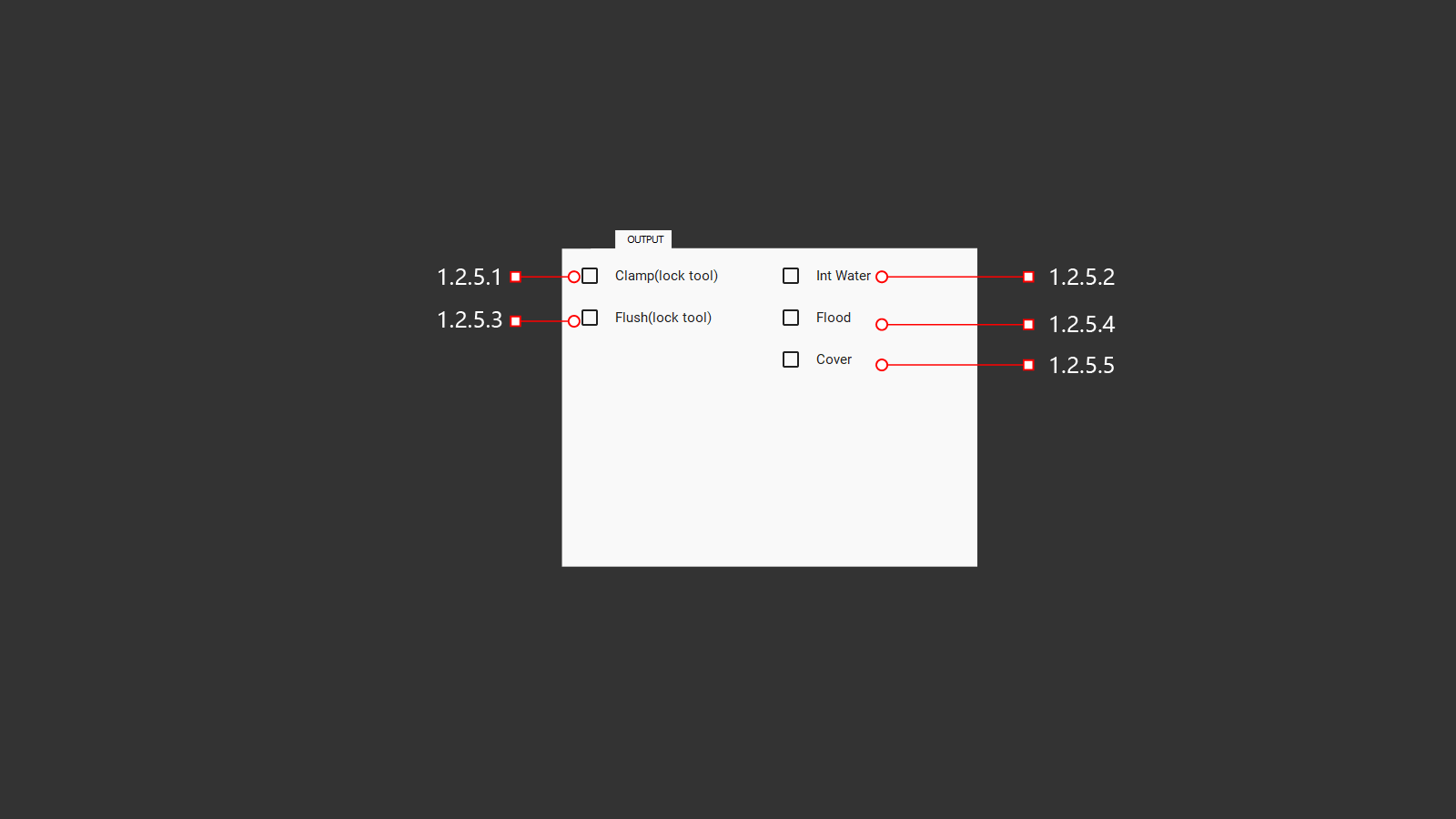
A tab with output signals for various machine functions. The operator can use these signals to check and adjust settings.
1.2.5.1 CLAMP (lock tool)
Button for fixing the tool clamp (for spindles with automatic changer)
1.2.5.2 INT WATER
Turning on the water to cool the tool through the central hole. Water is supplied through the center of the spindle with air supply to clean the tube after the water is turned off. When turned on, the operator can adjust the air pressure for the required balance.
1.2.5.3 FLUSH (lock tool)
Button for cleaning the tool clamp (for spindles with automatic changer)
1.2.5.4 FLOOD
Turning on all instrument cooling systems: these are the internal and external cooling supplies. They help the operator to adjust the cooling direction of the tool to produce high-quality work and results.
1.2.5.5 COVER
???
1.2.6 JOINT
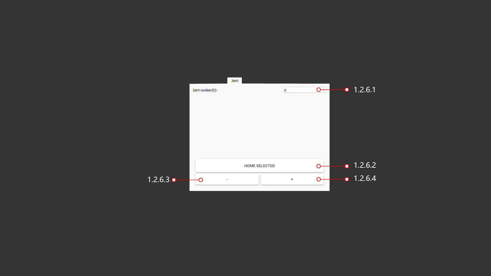
The servomotor control tab allows you to exceed the limits in case of an error or if the operator needs to control each axis of the machine individually.
1.2.6.1 JOINT NUMBER (x)
When clicked, a tab will open with a selection of the servo motor to control. In the case of the Y-axis, the movement must be carried out with extreme care, because the Y-axis controls two servomotors.
1.2.6.2 HOME SELECTED
A button that will move the axes back to their home position based on the parameters set in the machine, using axis position limit sensors.
1.2.6.3 -
A button to move the selected machine axis in the negative direction. Move with a small feed and be careful.
1.2.6.4 +
A button to move the selected machine axis in a positive direction. Move with a small feed and be careful.
1.2.7 CONTROL
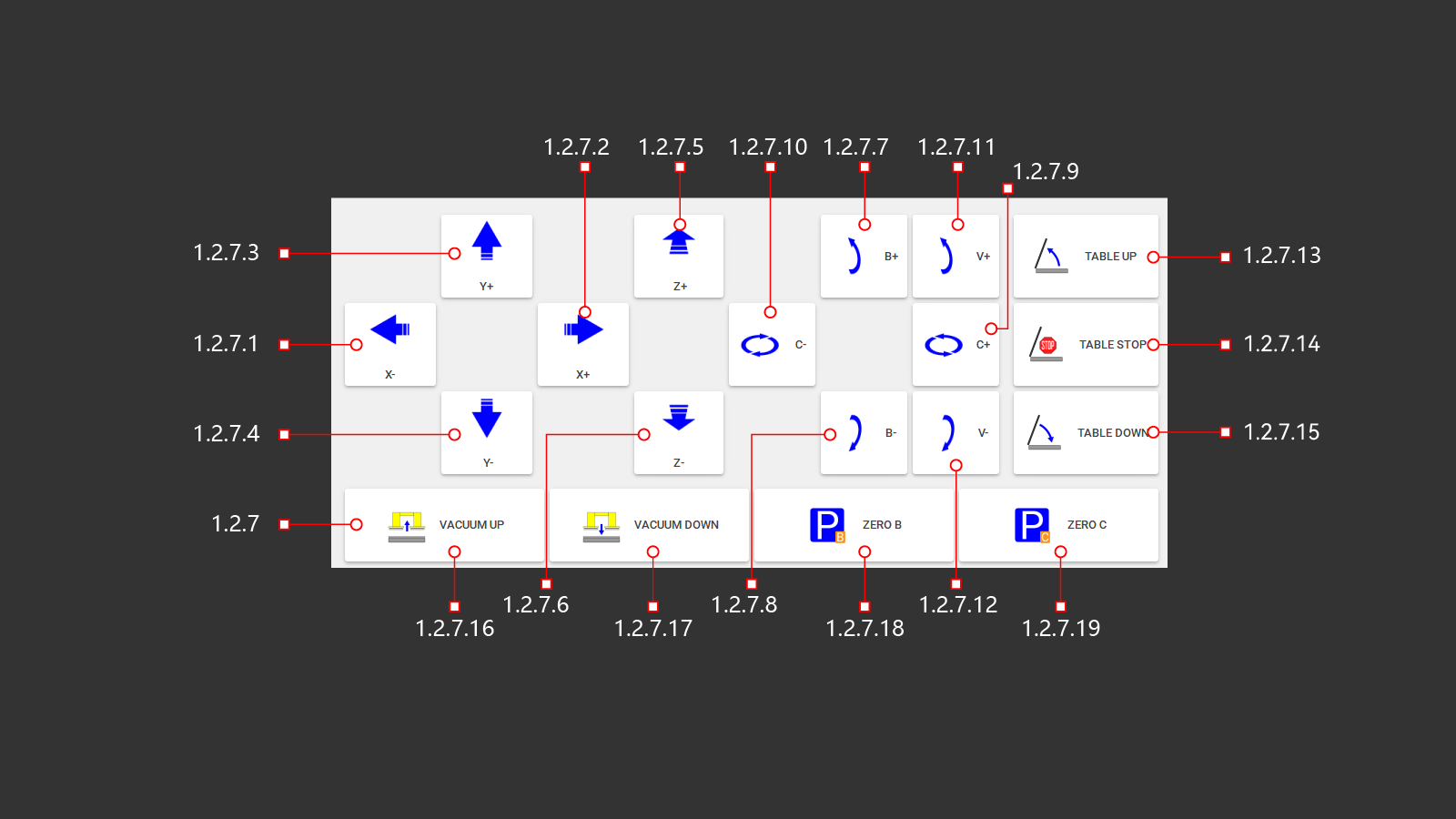 The operator's manual controls the machine. The operator can adjust the position of the selected cutting tool and perform necessary cutting operations. It is important to raise the work table for convenient loading of processed material and lower it with the material for further work. The operator has access to vacuum suction cups to move the material manually. There is an ability to return the C and B axes to their home positions after moving them manually.
1.2.7.1 X+
Controls the movement of the machine along the coordinate axes in the selected direction.
1.2.7.2 X-
Controls the movement of the machine along the coordinate axes in the selected direction.
1.2.7.3 Y+
Controls the movement of the machine along the coordinate axes in the selected direction.
1.2.7.4 Y-
Controls the movement of the machine along the coordinate axes in the selected direction.
1.2.7.5 Z+
Controls the movement of the machine along the coordinate axes in the selected direction.
1.2.7.6 Z-
Controls the movement of the machine along the coordinate axes in the selected direction.
1.2.7.7 B+
Control of spindle tilt along coordinate axes in the selected direction.
1.2.7.8 B-
Control of spindle tilt along coordinate axes in the selected direction.
1.2.7.9 C+
Control of spindle rotation along coordinate axes in the selected direction.
1.2.7.10 C-
Control of spindle rotation along coordinate axes in the selected direction.
1.2.7.11 V+
Controlling the tilt of the water jet module along the coordinate axes in the selected direction.
1.2.7.12 V-
Controlling the tilt of the water jet module along the coordinate axes in the selected direction.
1.2.7.13 TABLE UP
A button to raise the desktop. The hydraulic pump is turned on and the distribution valve directs the oil into the cylinders to start the lifting mechanism of the worktable.
1.2.7.14 TABLE STOP
A button to stop the operation of the lifting and lowering mechanism of the desktop. After pressing, the hydraulic pump turns off and the hydraulic distributor switches to the neutral position.
1.2.7.15 TABLE DOWN
The button for lowering the desktop. The hydraulic pump is turned on and the distribution valve directs the oil into the cylinders to start the lowering mechanism of the working table.
1.2.7.16 VACUUM UP
The operator uses a button to activate the vacuum suction cups to move the material. Once activated, the system lowers the vacuum suction cups into their working position using pneumatic cylinders. To visualize the operation, a photo of the material on the desktop is displayed on the screen. This allows the user to see where the suction cups are relative to the material and the table. Depending on the vacuum generation system in use, the vacuum pump or air supply to the vacuum generators may be turned on. Material movement operations should be carried out with a low rate of movement along the desired axes.
1.2.7.17 VACUUM DOWN
The button is necessary for the operator to put the lifted object in the moved place on the desktop. After pressing, the machine will automatically lower the material onto the worktable, the vacuum generation system will turn off, this is turning off the vacuum pump or turning off the air supply to the vacuum generators. The machine will lower the material and raise the vacuum system to standby mode using pneumatic cylinders.
1.2.7.18 ZERO B
After pressing this button, the machine will move along the selected axis B to the position sensor and return to the starting position relative to the set parameters.
1.2.7.19 ZERO C
After pressing this button, the machine will move along the selected axis C to the position sensor and return to the starting position relative to the set parameters.
1.3 AUTO
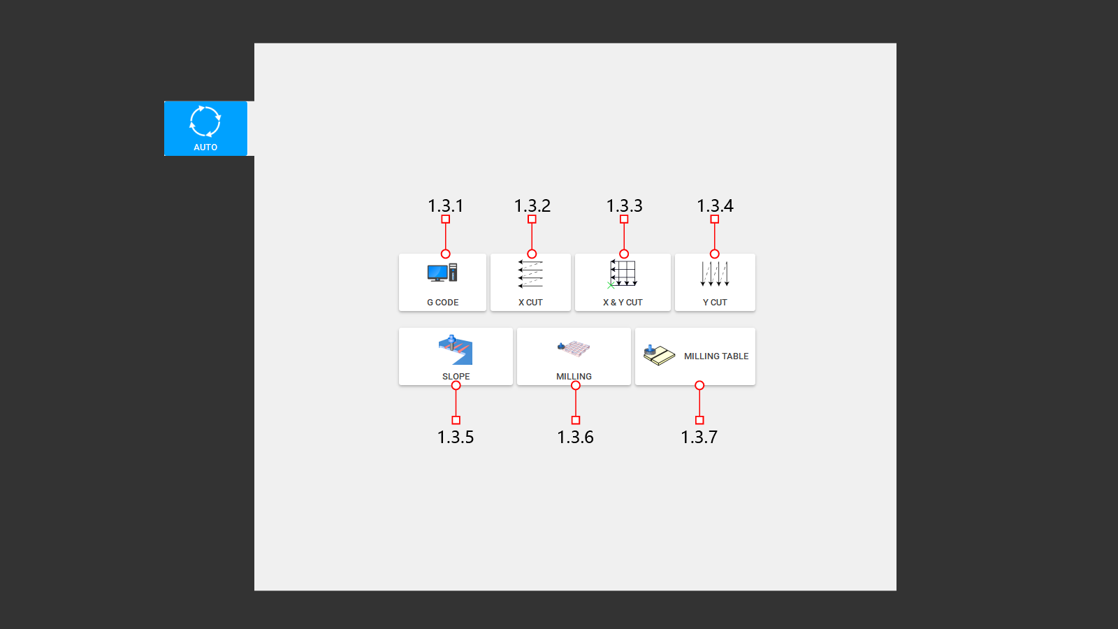 This tab displays the main built-in tabs for writing automatic control programs. Programs can be downloaded from a previously written program or you can create a control program directly on the machine using your own data for cutting and milling.
1.3.1 G CODE
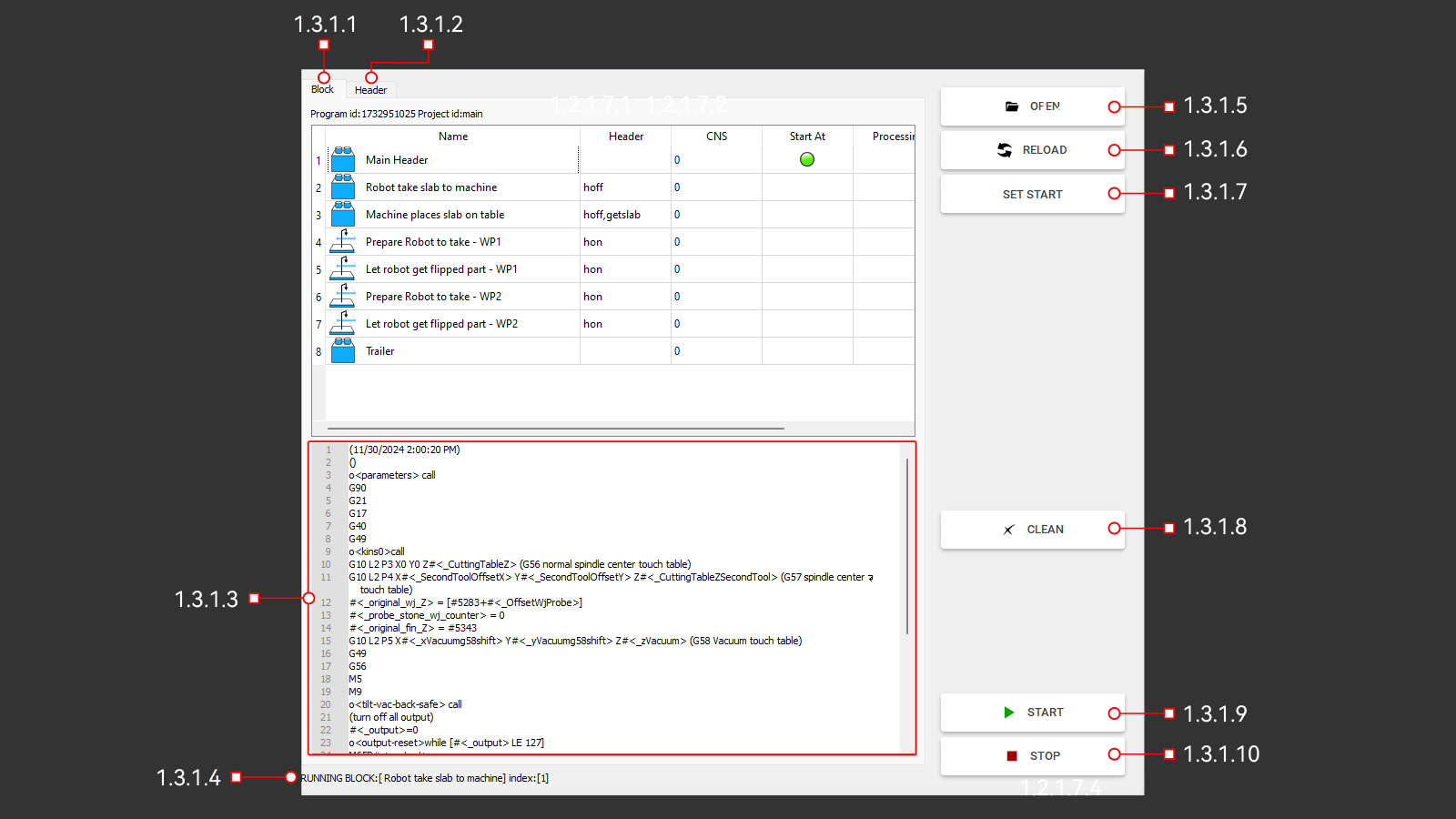 This tab opens a window to download the program written for the machine in the Pegasus software. The window contains the main controls and shows the progress of the downloaded program when it is being executed.
1.3.1.1 BLOCK
This is a block of machine actions according to a written program divided by the number of control commands required for the machine.
1.3.1.2 HEADER
1.3.1.3 CODE
This window displays programs in the form of G codes. Here you can view the actions of the machine when executing the program. The window displays data that can be useful for the operator and the machine operation before starting the program.
1.3.1.4 INFO
The line displays the command that the machine is currently executing.
1.3.1.5 OPEN
The button opens a folder with written programs for the machine. In this folder, the operator must select the necessary program to perform the work in automatic mode.
1.3.1.6 RELOAD
With this button, the operator can resume the previously selected program. This is necessary if any changes have been made to the program and it was saved with the same name. The machine will simply update the data for this program.
1.3.1.7 SET START
With this button, the operator can select any line in the Block window and the machine will execute programs from this location. To do this, you must first select the desired program line and press Set start. A green marker should appear on this line, which means that the operator has chosen to start the program from the specified location.
1.3.1.8 CLEAN
The button is necessary to clear the machine's memory of the downloaded program. Deletes it from the display block, but does not delete it from the folder with written programs.
1.3.1.9 START
A button to start the execution of the downloaded program. The program will start running from the very beginning or from the location selected by the operator. The machine will execute all commands that are written according to the program, measuring the diameter or length of the tool, checking the name of the tools. It will move to the required location, turn on the spindle and cooling, and start working.
1.3.1.10 STOP
A button to stop the program at the current time. The machine will stop in any position and at any time during the execution of the program. All devices used for operation will stop working. Stopping the movement along the axes, turning off the spindle and cooling the tool. On the Block tab, the operator will see the stop step. It will be marked with a green marker.
1.3.2 X CUT
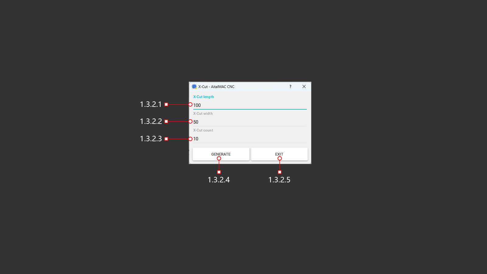 A button to open the menu to create a program for automatic cutting of the material. The operator has the option to use the built-in compiler to create simple programs. For linear cuts along the X-axis. The icon shows the program execution diagram, from right to left and up. This function is used with a cutting disc. It is convenient for cutting the material into identical strips.
1.3.2.1 X-CUT LENGTH
In the line, you must specify the length of the cut to be performed. The starting point of the cut will occur from the actual position of the cutting tool of the machine above the material.
1.3.2.2 X-CUT WIDTH
The line must specify the width of the required cut-out part. After executing the length-cutting command, the machine will rise to a safe height and move to the starting point along the X-axis and offset along the Y-axis with the distance indicated in the row.
1.3.2.3 X-CUT COUNT
The number of parts that need to be made must be specified in the line. This will be the number of repetitions of the first two commands to execute the program.
1.3.2.4 GENERATE
A button for creating a control program to perform tasks based on previously entered cutting parameters. After clicking, the operator will be able to see the program G-code and visualization on the screen in the upper right corner.
1.3.2.5 EXIT
Exit the menu without creating and saving a program for cutting the material. Return to the previous menu.
1.3.3 X&Y CUT
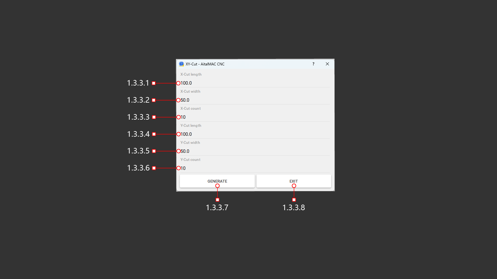 A button to open the menu to create a program for automatic cutting of the material. The operator has the option to use the built-in compiler to create simple programs. For linear cuts along the X and Y axes, the program execution diagram is shown on the icon, from right to left and up. This function is used with a cutting disc. A cross laser is used as the starting point for creating the program. To cut along the Y axis, the machine head will be rotated 90° along the C axis. It is convenient for cutting the material into identical squares or rectangles.
1.3.3.1 X-CUT LENGTH
In the line, you must specify the length of the cut to be performed. The starting point of the cut will be the position of the laser cross.
1.3.3.2 X-CUT WIDTH
The line must specify the width of the required cut-out part. After executing the length-cutting command, the machine will rise to a safe height and move to the starting point along the X-axis and offset along the Y-axis with the distance indicated in the row.
1.3.3.3 X-CUT COUNT
The number of parts that need to be made must be specified in the line. This will be the number of repetitions of the first two commands to execute the program.
1.3.3.4 Y-CUT LENGTH
In the line, you must specify the length of the cut to be performed. The starting point of the cut will be the position of the laser cross.
1.3.3.5 Y-CUT WIDTH
The line must specify the width of the required cut-out part. After executing the length-cutting command, the machine will rise to a safe height and move to the starting point along the X-axis and offset along the Y-axis with the distance indicated in the row.
1.3.3.6 Y-CUT COUNT
The number of parts that need to be made must be specified in the line. This will be the number of repetitions of the first two commands to execute the program.
1.3.3.7 GENERATE
A button for creating a control program to perform tasks based on previously entered cutting parameters. After clicking, the operator will be able to see the program G-code and visualization on the screen in the upper right corner.
1.3.3.8 EXIT
Exit the menu without creating and saving a program for cutting the material. Return to the previous menu.
1.3.4 Y CUT
 A button to open the menu to create a program for automatic cutting of the material. The operator has the option to use the built-in compiler to create simple programs. For linear cuts along the Y-axis. To cut along the Y axis, the machine head will be rotated 90° along the C axis. The icon shows the program execution diagram, from right to left and up. This function is used with a cutting disc.
1.3.4.1 Y-CUT LENGTH
In the line, you must specify the length of the cut to be performed. The starting point of the cut will occur from the actual position of the cutting tool of the machine above the material.
1.3.4.2 Y-CUT WIDTH
The line must specify the width of the required cut-out part. After executing the length-cutting command, the machine will rise to a safe height and move to the starting point along the X-axis and offset along the Y-axis with the distance indicated in the row.
1.3.4.3 Y-CUT COUNT
The number of parts that need to be made must be specified in the line. This will be the number of repetitions of the first two commands to execute the program.
1.3.4.4 GENERATE
A button for creating a control program to perform tasks based on previously entered cutting parameters. After clicking, the operator will be able to see the program G-code and visualization on the screen in the upper right corner.
1.3.4.5 EXIT
Exit the menu without creating and saving a program for cutting the material. Return to the previous menu.
1.3.5 SLOPE
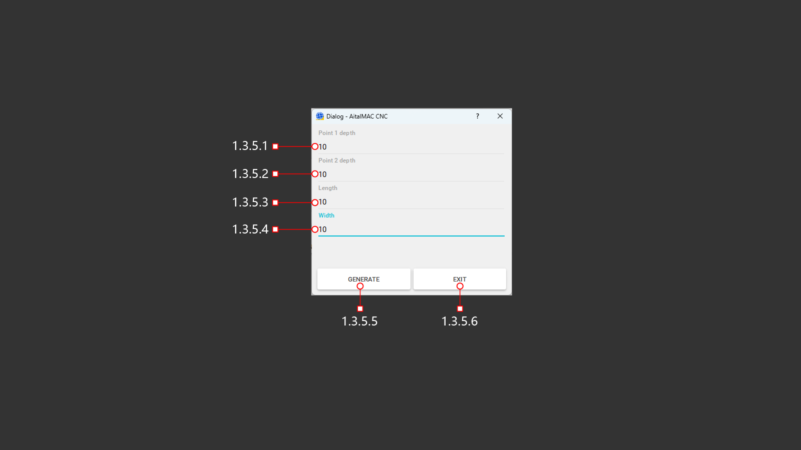
1.3.5.1 POINT 1 DEPTH
Setting the depth at the starting point for the slope
1.3.5.2 POINT 2 DEPTH
Setting the depth at the end point for a slope
1.3.5.3 LENGTH
Setting the cutting length for slope
1.3.5.4 WIDTH
Setting the cutting width for slope
1.3.5.5 GENERATE
Create G-code to perform cutting according to specified parameters
1.3.5.6 EXIT
Output from built-in cutting G-code generator
1.3.6 MILLING
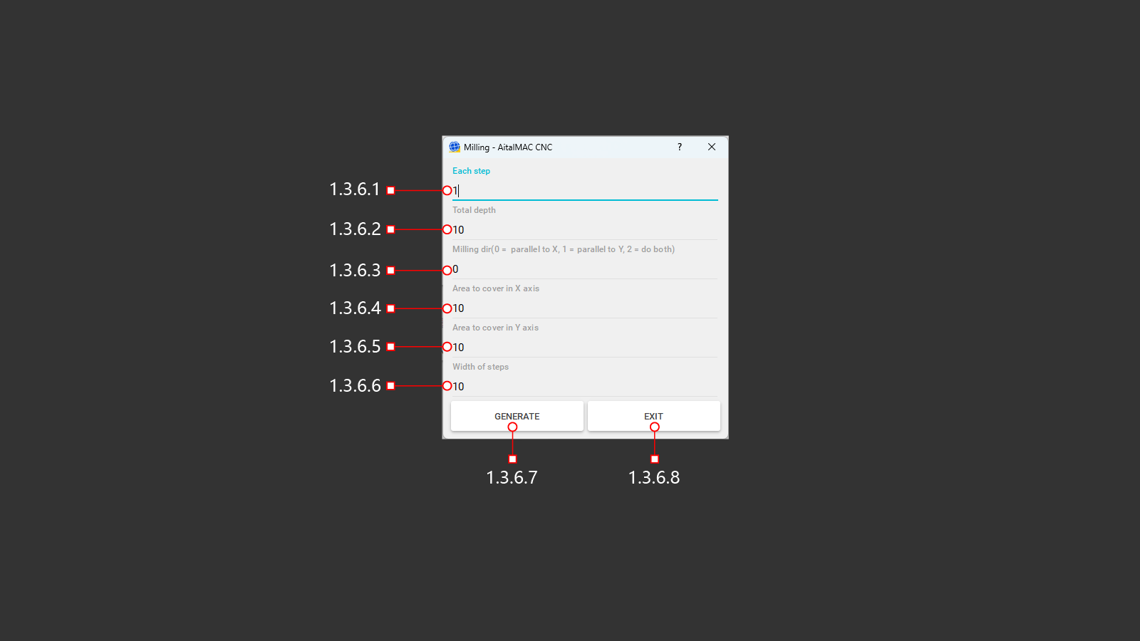
1.3.6.1 EACH STEP
Step depth per milling pass
1.3.6.2 TOTAL DEPTH
Full depth for milling
1.3.6.3 MILLING DIRECTION
Setting the milling direction. Horizontal x-axis (0), vertical y-axis (1) or two axes in turn (2)
1.3.6.4 AREA TO COVER IN X AXIS
Milling length along x axis
1.3.6.5 AREA TO COVER IN Y AXIS
Milling length along y axis
1.3.6.6 WIDTH OF STEPS
Setting the cutting width for milling
1.3.6.7 GENERATE
Create a G-code to perform milling according to the specified parameters.
1.3.6.8 EXIT
Output from built-in cutting G-code generator
1.3.7 MILLING TABLE

1.3.7.1 EACH STEP
Step depth per milling pass
1.3.7.2 TOTAL DEPTH
Full depth for milling
1.3.7.3 MILLING DIRECTION
Setting the milling direction. Horizontal x-axis (0), vertical y-axis (1) or two axes in turn (2)
1.3.7.4 AREA TO COVER IN X AXIS
Milling length along x axis
1.3.7.5 AREA TO COVER IN Y AXIS
Milling length along y axis
1.3.7.6 WIDTH OF STEPS
Setting the cutting width for milling
1.3.7.7 START X
Coordinates of the position of the tool to start milling along the x axis
1.3.7.8 START Y
Coordinates of the position of the tool to start milling along the y axis
1.3.7.9 PROBE MILLING TOOL
Use of checking the length of the tool used to fine-tune the operation of the machine according to the program.
1.3.7.10 CURRENT POSITION
Using the current machine position along the x and y axes to start the program
1.3.7.11 GENERATE
Create a G-code to perform milling according to the specified parameters.
1.3.7.12 EXIT
Output from built-in cutting G-code generator
1.4 MDI
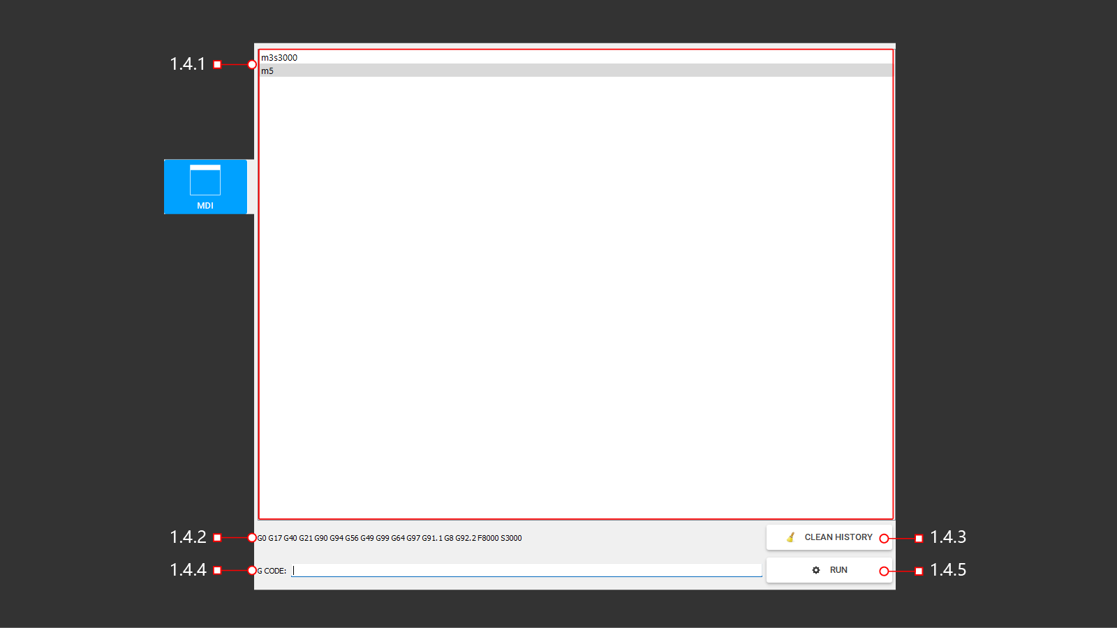
1.4.1 LIST
Window to view the last command and previously used ones
1.4.2 INFO
Possibly used and examples of G codes
1.4.3 CLEAN
Cleaning info window
1.4.4 G CODE
Line for entering g command code
1.4.5 RUN
Run the entered G code command
1.5 I/O
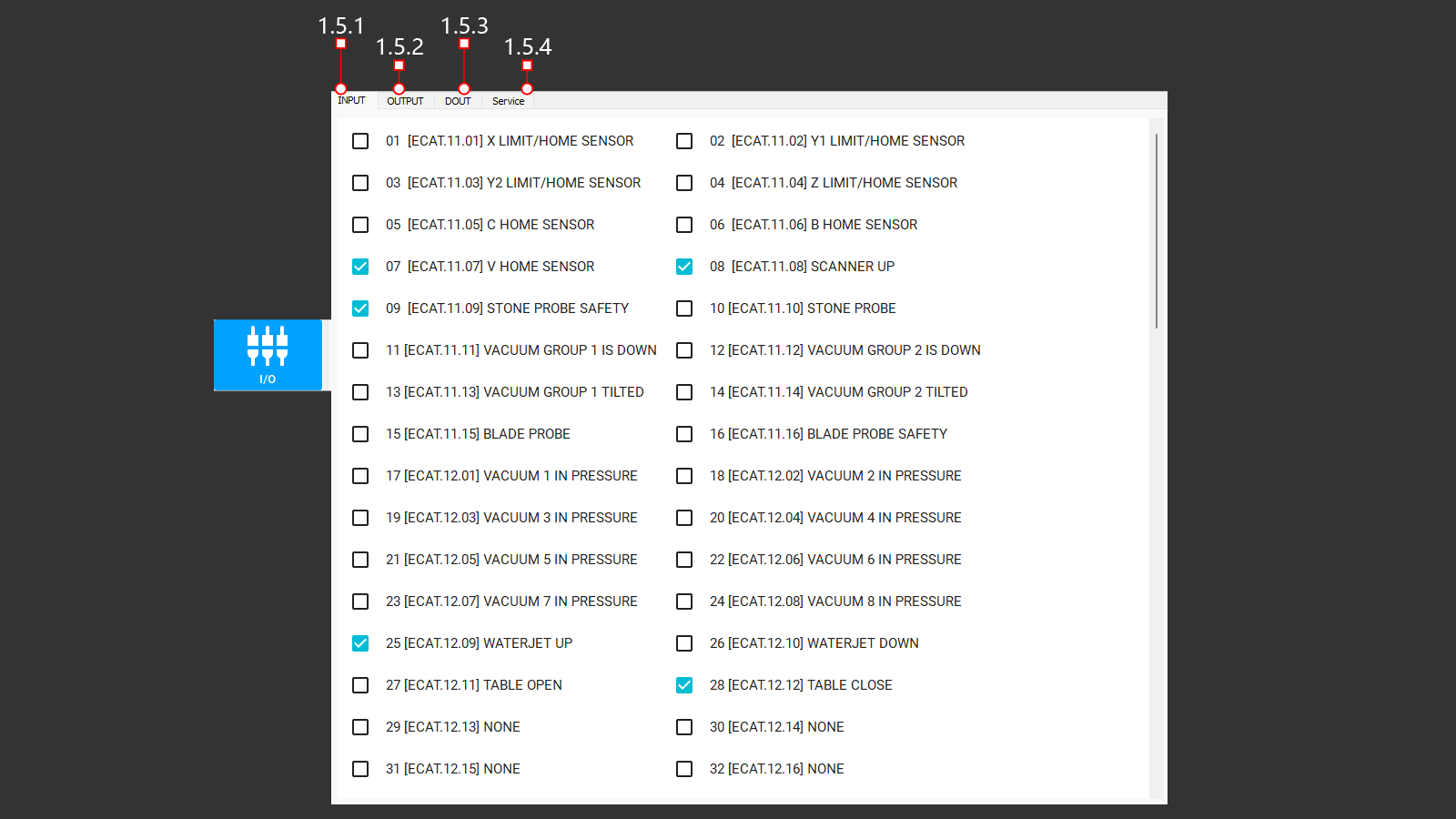
1.5.1 INPUT (1-32)
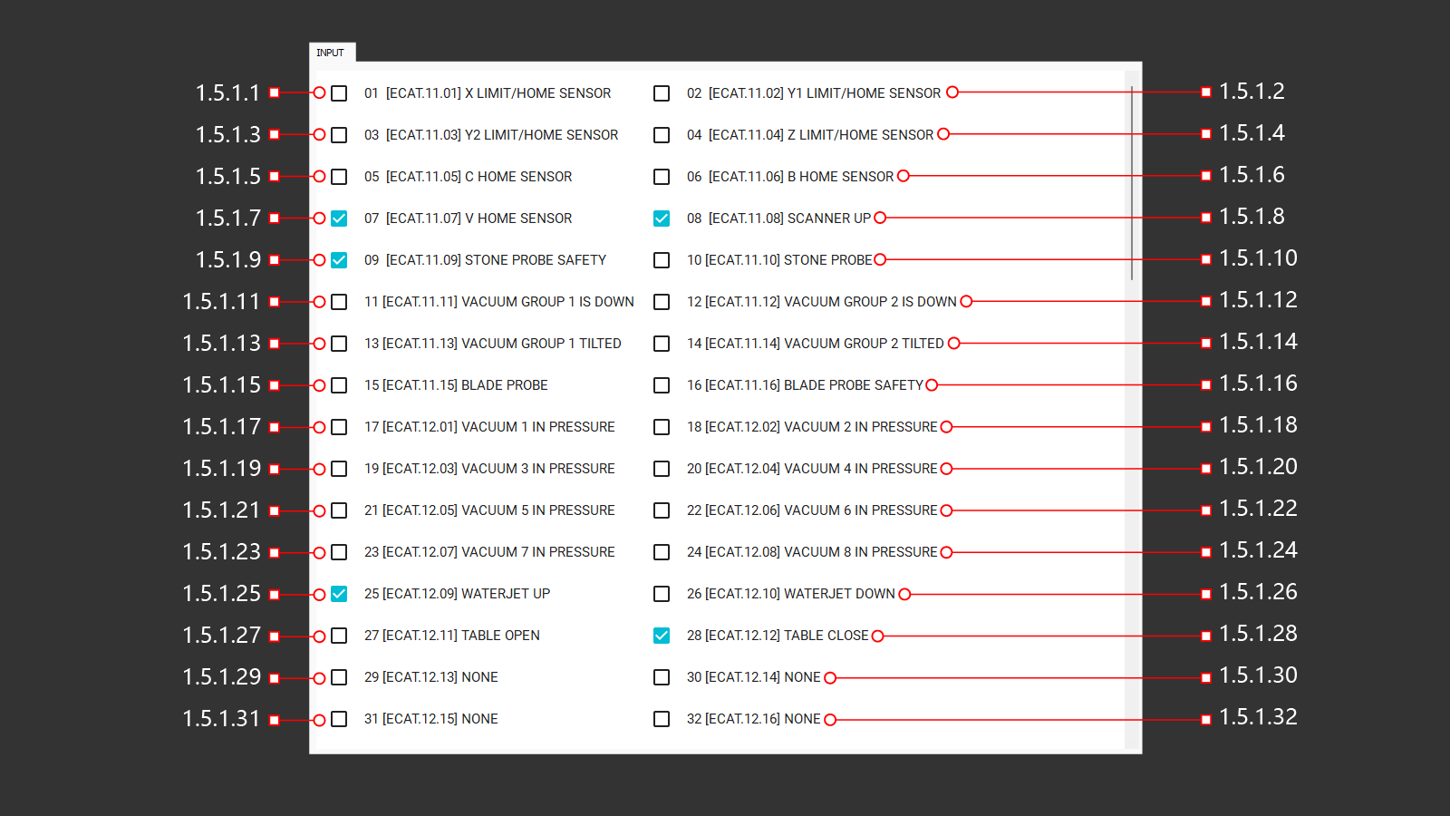
1.5.1.1 01 [ECAT.11.01] X LIMIT/HOME SENSOR
Input signal from the sensor along the x axis.
1.5.1.2 02 [ECAT.11.02] Y1 LIMIT/HOME SENSOR
Input signal from the sensor along the y1 axis.
1.5.1.3 03 [ECAT.11.03] Y2 LIMIT/HOME SENSOR
Input signal from the sensor along the y2 axis.
1.5.1.4 04 [ECAT.11.04] Z LIMIT/HOME SENSOR
Input signal from the sensor along the z axis.
1.5.1.5 05 [ECAT.11.05] C HOME SENSOR
Input signal from the sensor along the c axis.
1.5.1.6 06 [ECAT.11.06] B HOME SENSOR
Input signal from the sensor along the b axis.
1.5.1.7 07 [ECAT.11.07] V HOME SENSOR
Input signal from the sensor along the v axis.
1.5.1.8 08 [ECAT.11.08] SCANNER UP
Input signal from the sensor on the air cylinder to determine the position at the top.
1.5.1.9 09 [ECAT.11.09] STONE PROBE SAFETY
Input signal from the sensor on the air cylinder to determine the position at the top.
1.5.1.10 10 [ECAT.11.10] STONE PROBE
Input signal from the sensor on the air cylinder to determine the position at the bottom.
1.5.1.11 11 [ECAT.11.11] VACUUM GROUP 1 IS DOWN
Input signal from the sensor on the air cylinder to determine the position at the bottom.
1.5.1.12 12 [ECAT.11.12] VACUUM GROUP 2 IS DOWN
Input signal from the sensor on the air cylinder to determine the position at the bottom.
1.5.1.13 13 [ECAT.11.13] VACUUM GROUP 1 TILTED
Input signal from the sensor on the air cylinder to determine the position at the bottom.
1.5.1.14 14 [ECAT.11.14] VACUUM GROUP 2 TILTED
Input signal from the sensor on the air cylinder to determine the position at the bottom.
1.5.1.15 15 [ECAT.11.15] BLADE PROBE
Input signal from the sensor on the air cylinder to determine the position at the bottom 1.
1.5.1.16 16 [ECAT.11.16] BLADE PROBE SAFETY
Input signal from the sensor on the air cylinder to determine the position at the bottom2 .
1.5.1.17 17 [ECAT.12.01] VACUUM 1 IN PRESSURE
Input signal from the sensor on the vacuum generator, switching on and off.
1.5.1.18 18 [ECAT.12.02] VACUUM 2 IN PRESSURE
Input signal from the sensor on the vacuum generator, switching on and off.
1.5.1.19 19 [ECAT.12.03] VACUUM 3 IN PRESSURE
Input signal from the sensor on the vacuum generator, switching on and off.
1.5.1.20 20 [ECAT.12.04] VACUUM 4 IN PRESSURE
Input signal from the sensor on the vacuum generator, switching on and off.
1.5.1.21 21 [ECAT.12.05] VACUUM 5 IN PRESSURE
Input signal from the sensor on the vacuum generator, switching on and off.
1.5.1.22 22 [ECAT.12.06] VACUUM 6 IN PRESSURE
Input signal from the sensor on the vacuum generator, switching on and off.
1.5.1.23 23 [ECAT.12.07] VACUUM 7 IN PRESSURE
Input signal from the sensor on the vacuum generator, switching on and off.
1.5.1.24 24 [ECAT.12.08] VACUUM 8 IN PRESSURE
Input signal from the sensor on the vacuum generator, switching on and off.
1.5.1.25 25 [ECAT.12.09] WATERJET UP
Input signal from the sensor on the air cylinder to determine the position at the top.
1.5.1.26 26 [ECAT.12.10] WATERJET DOWN
Input signal from the sensor on the air cylinder to determine the position at the bottom.
1.5.1.27 27 [ECAT.12.11] TABLE OPEN
Input signal from the sensor on the hydraulic cylinder to determine the position of the open table.
1.5.1.28 28 [ECAT.12.12] TABLE CLOSE
Input signal from the sensor on the hydraulic cylinder to determine the down position.
1.5.1.29 29 [ECAT.12.13] NONE
The input signal on the control card is not assigned
1.5.1.30 30 [ECAT.12.14] NONE
The input signal on the control card is not assigned
1.5.1.31 31 [ECAT.12.15] NONE
The input signal on the control card is not assigned
1.5.1.32 32 [ECAT.12.16] NONE
The input signal on the control card is not assigned
1.5.1 INPUT (33-64)
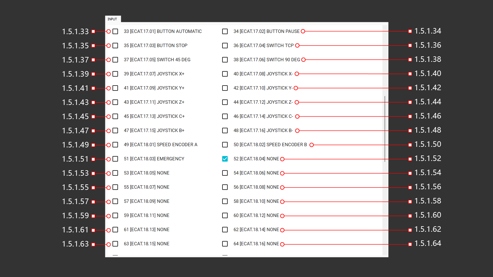
1.5.1.33 33 [ECAT.17.01] BUTTON AUTOMATIC
1.5.1.34 34 [ECAT.17.02] BUTTON PAUSE
1.5.1.35 35 [ECAT.17.03] BUTTON STOP
1.5.1.36 36 [ECAT.17.04] SWITCH TCP
1.5.1.37 37 [ECAT.17.05] SWITCH 45 DEG
1.5.1.38 38 [ECAT.17.06] SWITCH 90 DEG
1.5.1.39 39 [ECAT.17.07] JOYSTICK X+
1.5.1.40 40 [ECAT.17.08] JOYSTICK X-
1.5.1.41 41 [ECAT.17.09] JOYSTICK Y+
1.5.1.42 42 [ECAT.17.10] JOYSTICK Y-
1.5.1.43 43 [ECAT.17.11] JOYSTICK Z+
1.5.1.44 44 [ECAT.17.12] JOYSTICK Z-
1.5.1.45 45 [ECAT.17.13] JOYSTICK C+
1.5.1.46 46 [ECAT.17.14] JOYSTICK C-
1.5.1.47 47 [ECAT.17.15] JOYSTICK B+
1.5.1.48 48 [ECAT.17.16] JOYSTICK B-
1.5.1.49 49 [ECAT.18.01] SPEED ENCODER A
1.5.1.50 50 [ECAT.18.02] SPEED ENCODER B
1.5.1.51 51 [ECAT.18.03] EMERGENCY
1.5.1.52 52 [ECAT.18.04] NONE
The input signal on the control card is not assigned
1.5.1.53 53 [ECAT.18.05] NONE
The input signal on the control card is not assigned
1.5.1.54 54 [ECAT.18.06] NONE
The input signal on the control card is not assigned
1.5.1.55 55 [ECAT.18.07] NONE
The input signal on the control card is not assigned
1.5.1.56 56 [ECAT.18.08] NONE
The input signal on the control card is not assigned
1.5.1.57 57 [ECAT.18.09] NONE
The input signal on the control card is not assigned
1.5.1.58 58 [ECAT.18.10] NONE
The input signal on the control card is not assigned
1.5.1.59 59 [ECAT.18.11] NONE
The input signal on the control card is not assigned
1.5.1.60 60 [ECAT.18.12] NONE
The input signal on the control card is not assigned
1.5.1.61 61 [ECAT.18.13] NONE
The input signal on the control card is not assigned
1.5.1.62 62 [ECAT.18.14] NONE
The input signal on the control card is not assigned
1.5.1.63 63 [ECAT.18.15] NONE
The input signal on the control card is not assigned
1.5.1.64 64 [ECAT.18.16] NONE
The input signal on the control card is not assigned
1.5.1 INPUT (65-96)
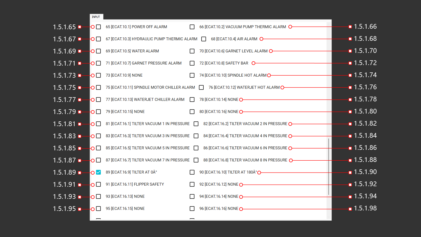
1.5.1.65 65 [ECAT.10.1] POWER OFF ALARM
1.5.1.66 66 [ECAT.10.2] VACUUM PUMP THERMIC ALARM
1.5.1.67 67 [ECAT.10.3] HYDRAULIC PUNP THERMIC ALARM
1.5.1.68 68 [ECAT.10.4] AIR ALARM
1.5.1.69 69 [ECAT.10.5] WATER ALARM
1.5.1.70 70 [ECAT.10.6] GARNET LEVEL ALARM
1.5.1.71 71 [ECAT.10.7] GARNET PRESSURE ALARM
1.5.1.72 72 [ECAT.10.8] SAFETY BAR
1.5.1.73 73 [ECAT.10.9] NONE
The input signal on the control card is not assigned
1.5.1.74 74 [ECAT.10.10] SPINDLE HOT ALARM
1.5.1.75 75 [ECAT.10.11] SPINDLE MOTOR CHILLER ALARM
1.5.1.76 76 [ECAT.10.12] WATERJET HOT ALARM
1.5.1.77 77 [ECAT.10.13] WATERJET CHILLER ALARM
1.5.1.78 78 [ECAT.10.14] NONE
The input signal on the control card is not assigned
1.5.1.79 79 [ECAT.10.15] NONE
The input signal on the control card is not assigned
1.5.1.80 80 [ECAT.10.16] NONE
The input signal on the control card is not assigned
1.5.1.81 81 [ECAT.16.1] TILTER VACUUM 1 IN PRESSURE
1.5.1.82 82 [ECAT.16.2] TILTER VACUUM 2 IN PRESSURE
1.5.1.83 83 [ECAT.16.3] TILTER VACUUM 3 IN PRESSURE
1.5.1.84 84 [ECAT.16.4] TILTER VACUUM 4 IN PRESSURE
1.5.1.85 85 [ECAT.16.5] TILTER VACUUM 5 IN PRESSURE
1.5.1.86 86 [ECAT.16.6] TILTER VACUUM 6 IN PRESSURE
1.5.1.87 87 [ECAT.16.7] TILTER VACUUM 7 IN PRESSURE
1.5.1.88 88 [ECAT.16.8] TILTER VACUUM 8 IN PRESSURE
1.5.1.89 89 [ECAT.16.9] TILTER AT 0A°
1.5.1.90 90 [ECAT.16.10] TILTER AT 180A°
1.5.1.91 91 [ECAT.16.11] FLIPPER SAFETY
1.5.1.92 92 [ECAT.16.12] NONE
The input signal on the control card is not assigned
1.5.1.93 93 [ECAT.16.13] NONE
The input signal on the control card is not assigned
1.5.1.94 94 [ECAT.16.14] NONE
The input signal on the control card is not assigned
1.5.1.95 95 [ECAT.16.15] NONE
The input signal on the control card is not assigned
1.5.1.96 96 [ECAT.16.16] NONE
The input signal on the control card is not assigned
1.5.1 INPUT (97-108)
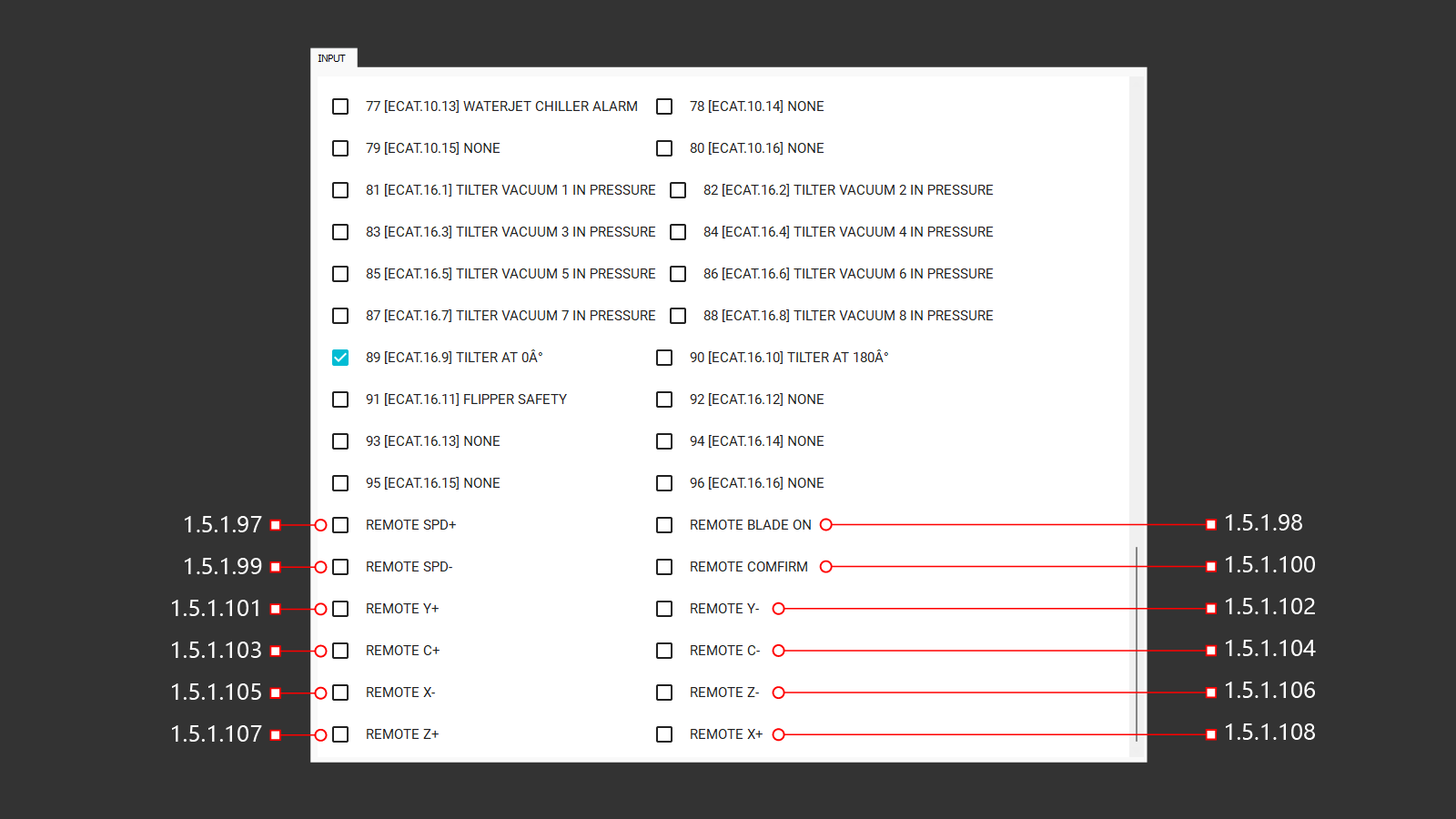
1.5.1.97 REMOTE SPD+
1.5.1.98 REMOTE BLADE ON
1.5.1.99 REMOTE SPD-
1.5.1.100 REMOTE CONFIRM
1.5.1.101 REMOTE Y+
1.5.1.102 REMOTE Y-
1.5.1.103 REMOTE C+
1.5.1.104 REMOTE C-
1.5.1.105 REMOTE X-
1.5.1.106 REMOTE Z-
1.5.1.107 REMOTE Z+
1.5.1.108 REMOTE X+
1.5.2 OUTPUT (1-32)
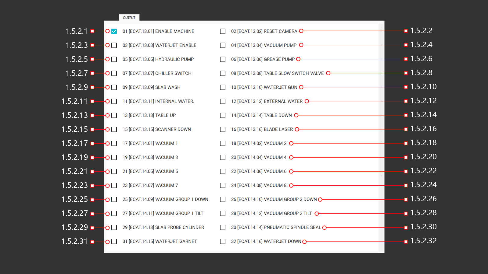
1.5.2.1 01 [ECAT.13.01] ENABLE MACHINE
1.5.2.2 02 [ECAT.13.02] RESET CAMERA
1.5.2.3 03 [ECAT.13.03] WATERJET ENABLE
1.5.2.4 04 [ECAT.13.04] VACUUM PUMP
1.5.2.5 05 [ECAT.13.05] HYDRAULIC PUMP
1.5.2.6 06 [ECAT.13.06] GREASE PUMP
1.5.2.7 07 [ECAT.13.07] CHILLER SWITCH
1.5.2.8 08 [ECAT.13.08] TABLE SLOW SWITCH VALVE
1.5.2.9 09 [ECAT.13.09] SLAB WASH
1.5.2.10 10 [ECAT.13.10] WATERJET GUN
1.5.2.11 11 [ECAT.13.11] INTERNAL WATER
1.5.2.12 12 [ECAT.13.12] EXTERNAL WATER
1.5.2.13 13 [ECAT.13.13] TABLE UP
1.5.2.14 14 [ECAT.13.14] TABLE DOWN
1.5.2.15 15 [ECAT.15.15] SCANER DOWN
1.5.2.16 16 [ECAT.13.16] BLADE LASER
1.5.2.17 17 [ECAT.14.01] VACUUM 1
1.5.2.18 18 [ECAT.14.02] VACUUM 2
1.5.2.19 19 [ECAT.14.03] VACUUM 3
1.5.2.20 20 [ECAT.14.04] VACUUM 4
1.5.2.21 21 [ECAT.14.05] VACUUM 5
1.5.2.22 22 [ECAT.14.06] VACUUM 6
1.5.2.23 23 [ECAT.14.07] VACUUM 7
1.5.2.24 24 [ECAT.14.08] VACUUM 8
1.5.2.25 25 [ECAT.14.09] VACUUM GROUP 1 DOWN
1.5.2.26 26 [ECAT.14.10] VACUUM GROUP 2 DOWN
1.5.2.27 27 [ECAT.14.11] VACUUM GROUP 1 TILT
1.5.2.28 28 [ECAT.14.12] VACUUM GROUP 2 TILT
1.5.2.29 29 [ECAT.14.13] SLAB PROBE CYLINDER
1.5.2.30 30 [ECAT.14.14] PNEUMATIC SPINDLE SEAL
1.5.2.31 31 [ECAT.14.15] WATERJET GARNET
1.5.2.32 32 [ECAT.14.16] WATERJET DOWN
1.5.2 OUTPUT (33-48)
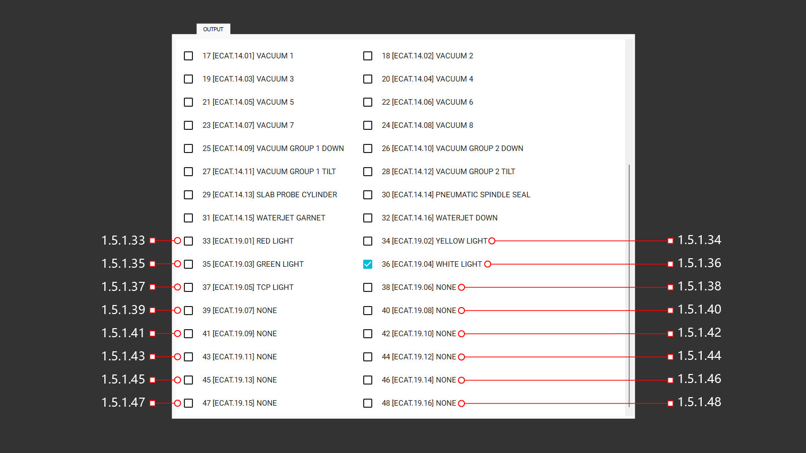
1.5.2.33 33 [ECAT.19.01] RED LIGHT
1.5.2.34 34 [ECAT.19.02] YELLOW LIGHT
1.5.2.35 35 [ECAT.19.03] GREEN LIGHT
1.5.2.36 36 [ECAT.19.04] WHITE LIGHT
1.5.2.37 37 [ECAT.19.05] TCP LIGHT
1.5.2.38 38 [ECAT.19.06] NONE
1.5.2.39 39 [ECAT.19.07] NONE
1.5.2.40 40 [ECAT.19.08] NONE
1.5.2.41 41 [ECAT.19.09] NONE
1.5.2.42 42 [ECAT.19.10] NONE
1.5.2.43 43 [ECAT.19.11] NONE
1.5.2.44 44 [ECAT.19.12] NONE
1.5.2.45 45 [ECAT.19.13] NONE
1.5.2.46 46 [ECAT.19.14] NONE
1.5.2.47 47 [ECAT.19.15] NONE
1.5.2.48 48 [ECAT.19.16] NONE
1.5.3 DOUT (1-16)
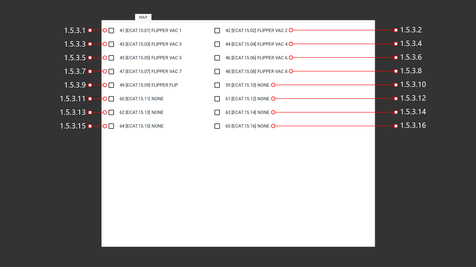
1.5.3.1 1 [ECAT.15.01] FLIPPER VAC 1
1.5.3.2 42 [ECAT.15.02] FLIPPER VAC 2
1.5.3.3 43 [ECAT.15.03] FLIPPER VAC 3
1.5.3.4 44 [ECAT.15.04] FLIPPER VAC 4
1.5.3.5 45 [ECAT.15.05] FLIPPER VAC 5
1.5.3.6 46 [ECAT.15.06] FLIPPER VAC 6
1.5.3.7 47 [ECAT.15.07] FLIPPER VAC 7
1.5.3.8 48 [ECAT.15.08] FLIPPER VAC 8
1.5.3.9 49 [ECAT.15.09] FLIPPER FLIP
1.5.3.10 59 [ECAT.15.10] NONE
1.5.3.11 60 [ECAT.15.11] NONE
1.5.3.12 61 [ECAT.15.12] NONE
1.5.3.13 62 [ECAT.15.13] NONE
1.5.3.14 63 [ECAT.15.14] NONE
1.5.3.15 64 [ECAT.15.15] NONE
1.5.3.16 65 [ECAT.15.16] NONE
1.5.4 SERVICE
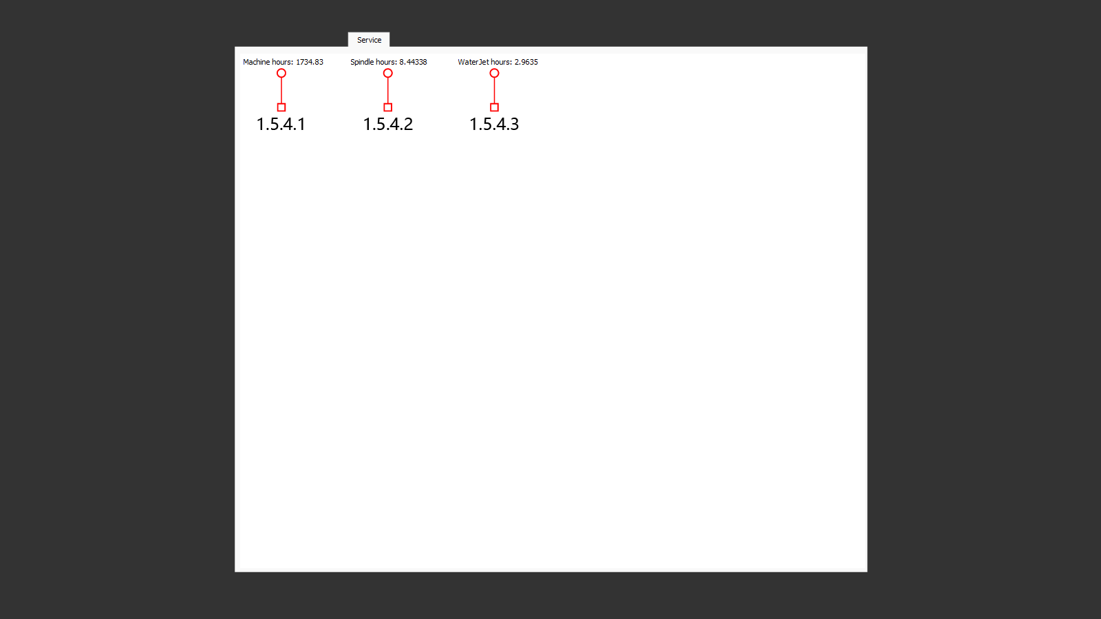
1.5.4.1 MACHINE HOURS
1.5.4.2 SPINDLE HOURS
1.5.4.3 WATERJET HOURS
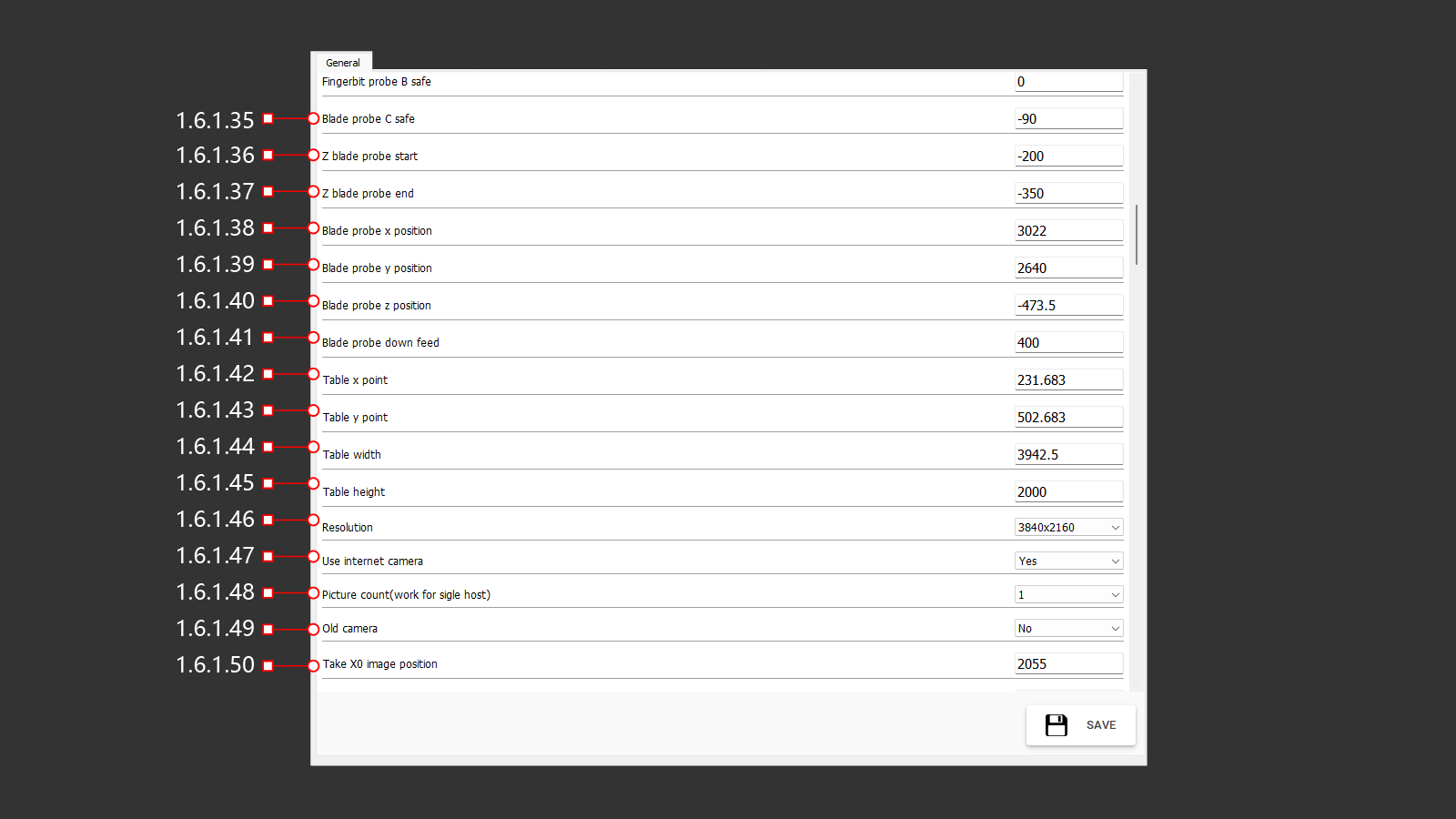
1.6 Parameters
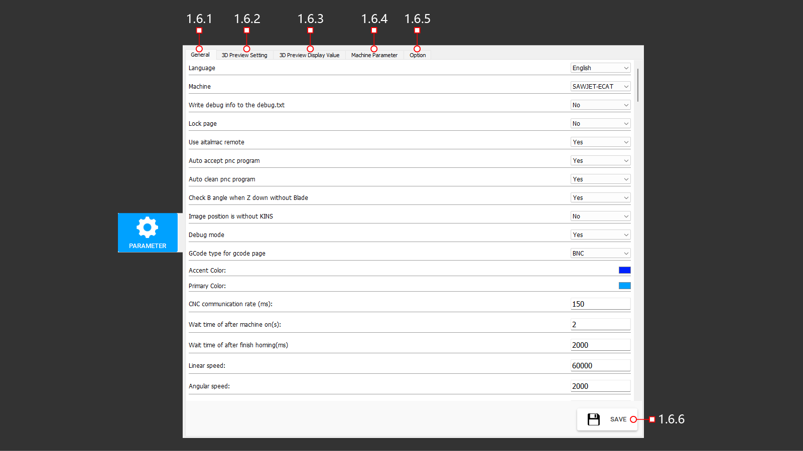
1.6.1 GENERAL (1-18)
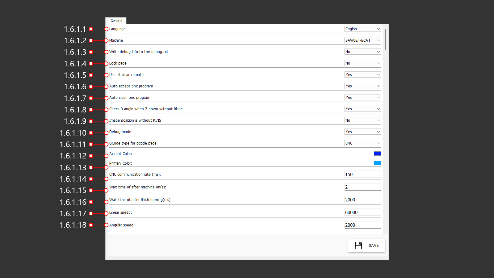
1.6.1.1 Language
1.6.1.2 Machine
1.6.1.3 Write debug info to the debug.txt
1.6.1.4 Lock page
1.6.1.5 Use aitalmac remote
1.6.1.6 Auto accept pnc program
1.6.1.7 Auto clean pnc program
1.6.1.8 Check B angle when Z down without Blade
1.6.1.9 Image position is without KINS
1.6.1.10 Debug mode
1.6.1.11 GCode type for gcode page
1.6.1.12 Accent Color
1.6.1.13 Primary Color
1.6.1.14 CNC communication rate (ms)
1.6.1.15 Wait time of after machine on (s)
1.6.1.16 Wait time of after finish homing (ms)
1.6.1.17 Linear speed
1.6.1.18 Angular speed
1.6.1 GENERAL (19-34)
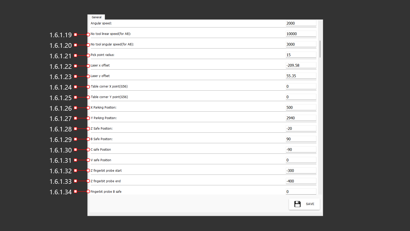
1.6.1.19 No tool linear speed (for A8)
1.6.1.20 No tool angular speed (for A8)
1.6.1.21 Pick point radius
1.6.1.22 Laser x offset
1.6.1.23 Laser y offset
1.6.1.24 Table corner X point (G56)
1.6.1.25 Table corner Y point (G56)
1.6.1.26 X Parking Position
1.6.1.27 Y Parking Position
1.6.1.28 Z Safe Position
1.6.1.29 B Safe Position
1.6.1.30 C safe Position
1.6.1.31 V safe Position
1.6.1.32 Z fingerbit probe start
1.6.1.33 Z fingerbit probe end
1.6.1.34 Fingerbit probe B safe
1.6.1 GENERAL (35-50)